 Excellent PLC


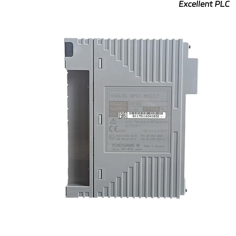
The Yokogawa ASI133 Analog Input Module is a 16-channel isolated analog input module used in Yokogawa CENTUM VP and CENTUM CS 3000 Distributed Control Systems (DCS). The module acquires standard 4–20 mA analog signals from field transmitters such as pressure, temperature, flow, level, and analytical instruments, converting them into digital values for process monitoring and control. Failures affecting the ASI133, field wiring, or transmitters may result in incorrect process measurements, unstable control loops, nuisance alarms, or complete loss of analog input signals.
Contents
- 1. Understanding Analog Input Faults
- 2. Common Failure Symptoms
- 3. Typical Causes
- 4. Initial Hardware Inspection
- 5. Current Loop Verification
- 6. Field Transmitter Inspection
- 7. Diagnostic Analysis
- 8. Recommended Troubleshooting Workflow
- 9. Corrective Actions
- 10. Functional Recovery Verification
- 11. Preventive Maintenance
- 12. Industrial Maintenance Case
- 13. Frequently Asked Questions
Understanding Analog Input Faults
The ASI133 continuously measures analog process signals and transfers digital values to the DCS controller. Faults may originate from failed transmitters, broken current loops, loose terminal connections, incorrect loop polarity, insufficient transmitter power, grounding problems, electrical noise, configuration errors, or internal module failures. A structured troubleshooting procedure should identify whether the fault exists in the transmitter, signal wiring, power supply, terminal assembly, or the ASI133 module.
Common Failure Symptoms
- Measured value remains fixed.
- Input displays 0 mA or full-scale value.
- Process value fluctuates continuously.
- Signal is unstable or noisy.
- Multiple channels fail simultaneously.
- DCS reports analog input diagnostic alarms.
- Measured value differs from field indicator.
- Loop alarm appears unexpectedly.
Typical Causes
- Faulty pressure, temperature, flow, or level transmitter.
- Broken 4–20 mA current loop.
- Loose terminal connections.
- Incorrect loop polarity.
- Insufficient transmitter power supply.
- Improper cable shielding or grounding.
- Configuration errors in the DCS.
- Damaged terminal assembly.
- Internal ASI133 hardware failure.
Initial Hardware Inspection
- Verify the ASI133 is correctly installed.
- Inspect module status indicators.
- Check terminal block installation.
- Verify cabinet grounding.
- Inspect cabinet temperature and ventilation.
- Review DCS diagnostic messages.
Current Loop Verification
- Measure loop current using a calibrated multimeter.
- Verify transmitter supply voltage.
- Inspect cable continuity.
- Verify terminal numbers.
- Check signal polarity.
- Inspect cable shielding and insulation.
Field Transmitter Inspection
- Verify transmitter calibration.
- Inspect transmitter power supply.
- Measure transmitter output current.
- Check impulse lines or sensing elements.
- Verify transmitter configuration.
- Confirm correct process operation.
Diagnostic Analysis
| Observed Condition | Possible Diagnosis |
|---|---|
| 0 mA input | Open circuit or transmitter power failure |
| Constant 20 mA reading | Short circuit, transmitter failure, or saturated output |
| Unstable measurement | Electrical noise, poor grounding, or faulty transmitter |
| Multiple channels fail | Power supply, terminal assembly, or module fault |
| Incorrect engineering value | Scaling or configuration error |
Recommended Troubleshooting Workflow
CHECK DCS DIAGNOSTICS
VERIFY MODULE STATUS
MEASURE LOOP CURRENT
VERIFY TRANSMITTER POWER
CHECK FIELD WIRING
VERIFY CONFIGURATION
TEST INPUT CHANNEL
CONFIRM NORMAL OPERATION
Corrective Actions
- Replace faulty transmitters.
- Repair broken current loops.
- Tighten loose terminal connections.
- Correct wiring polarity.
- Restore transmitter power supply.
- Improve grounding and cable shielding.
- Correct engineering configuration.
- Replace damaged terminal assemblies.
- Replace the ASI133 module if hardware failure is confirmed.
Functional Recovery Verification
- Verify accurate loop current measurements.
- Compare DCS values with field indicators.
- Check alarm functions.
- Verify all analog channels.
- Review diagnostic information.
- Monitor long-term measurement stability.
Preventive Maintenance
- Inspect terminals periodically.
- Check cable shielding and insulation.
- Verify transmitter calibration schedules.
- Review diagnostic history.
- Maintain cabinet grounding.
- Perform scheduled loop testing.
Industrial Maintenance Case
During routine operation of a refinery crude distillation unit, operators observed that a pressure transmitter displayed a constant 0% value in the DCS while the local pressure indicator showed normal process pressure.
Maintenance engineers measured the transmitter loop and found an open circuit caused by a loose terminal connection inside the marshalling cabinet. After tightening the terminal, verifying loop current, and checking transmitter calibration:
- The ASI133 channel immediately resumed normal operation.
- The pressure value matched the local field indicator.
- DCS diagnostic alarms cleared automatically.
- Stable process control was restored.
Frequently Asked Questions
Why does the ASI133 display 0 mA?
This is commonly caused by an open current loop, loss of transmitter power, broken field wiring, or a failed transmitter.
Why is the measured value unstable?
Unstable readings are usually caused by electrical interference, poor cable shielding, improper grounding, loose wiring, or transmitter instability.
What should be checked before replacing the ASI133?
Verify transmitter operation, loop current, power supply voltage, wiring continuity, terminal connections, engineering configuration, grounding, shielding, and DCS diagnostics before concluding that the module itself has failed.
Summary
Effective troubleshooting of the Yokogawa ASI133 Analog Input Module requires systematic inspection of transmitters, 4–20 mA current loops, power supplies, field wiring, terminal assemblies, grounding, engineering configuration, and DCS diagnostics. Regular preventive maintenance, loop calibration, and periodic verification ensure accurate analog signal acquisition and reliable long-term operation of Yokogawa CENTUM Distributed Control Systems.