

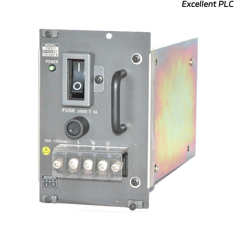
Industrial control systems rely heavily on the Yokogawa PW501 power supply module for stable DC output to field I/O and communication modules. While robust under normal conditions, seismic activity or mechanical vibrations can lead to sudden module failures or intermittent faults.
This article explores earthquake-related damage scenarios, examines repair feasibility, provides step-by-step replacement guidance, and offers preventive recommendations.
1. Real-World Earthquake Scenarios
1.1 Site Case Study
During a minor earthquake in a coastal manufacturing plant, several PW501 modules exhibited sudden voltage drops. Engineers found that vibrations caused partial disconnection of backplane contacts, leading to intermittent power loss across multiple I/O racks.
-
Cabinets mounted on uneven surfaces were most affected
-
Modules near the edges of racks experienced connector loosening
-
Shaking caused solder microfractures on some modules
1.2 Common Causes of Mechanical Shock Damage
-
Poorly secured cabinets or racks
-
Loose module seating in backplanes
-
Excessive vibration from nearby equipment (motors, compressors)
-
Transportation or handling during maintenance
Even moderate shocks can trigger immediate faults or latent failures.
2. Symptoms of Vibration-Related PW501 Failure
-
Sudden loss of module output or intermittent voltage drop
-
I/O communication errors
-
LED indicators blinking or off without apparent reason
-
Alarm logs indicating overcurrent or module fault
Unlike environmental damage (fire, water), these symptoms appear immediately after mechanical stress.
3. Repair Feasibility
-
Minor loose connectors may be corrected by reseating the module
-
Solder microfractures or PCB stress cracks → module replacement recommended
-
Do not attempt repair on modules with visible PCB stress or bent connectors
Engineering Tip: Mechanical stress often causes latent defects that can fail under load, making replacement the safest approach.
4. Field Replacement Procedure
4.1 Safety Precautions
-
Power down the system completely
-
Wear insulating gloves
-
Stabilize cabinet to prevent further vibration during replacement
4.2 Module Removal
-
Detach connectors carefully
-
Avoid hitting adjacent modules
4.3 Inspect Backplane and Connectors
-
Check for loose or damaged contacts
-
Inspect solder joints for microfractures
-
Replace any connectors showing signs of stress
4.4 Installing a New PW501
-
Monitor LED indicators and output voltage under normal load
-
Check connected I/O modules for stable operation
5. Preventive Recommendations
-
Secure cabinets and racks to withstand vibrations
-
Use anti-vibration mounts for high-risk areas
-
Inspect module seating after mechanical shocks or transportation
-
Consider redundant power modules to maintain uptime
6. Key Takeaways
Mechanical shock, whether from earthquakes or heavy vibration, can immediately compromise PW501 modules. Unlike water or fire, damage is often subtle but can lead to intermittent failures if not addressed.
-
Replacement is safer than repair for modules with mechanical stress
-
Proper cabinet mounting, anti-vibration measures, and post-event inspection reduce downtime
-
Document all incidents for future preventive planning