

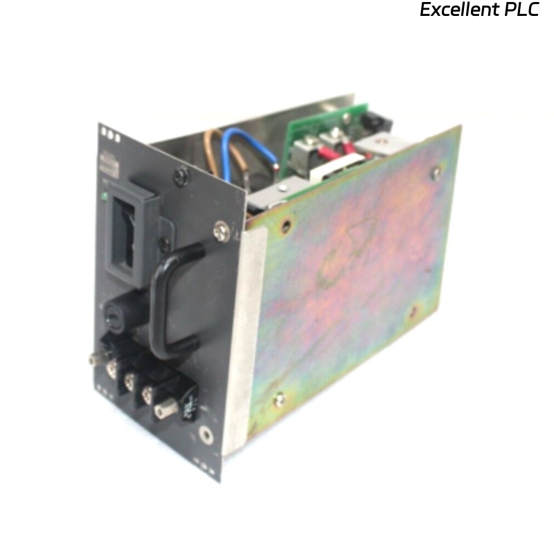
The Yokogawa PW501 is a 24 V DC, 5 A power supply module commonly used in distributed control systems. Human error remains one of the most frequent causes of module failure, particularly during maintenance or module replacement operations.
This article covers common operator mistakes, failure mechanisms, repair feasibility, replacement steps, and preventive measures.
1. How Human Error Damages PW501
1.1 Real-Life Cases
-
Hot-swapping while system live: causes overcurrent spikes up to 6–7 A, immediately triggering module protection
-
Incorrect insertion angle: leads to connector misalignment up to 0.8 mm, causing intermittent voltage drop
-
Loose screws or unfastened brackets: results in backplane vibration and module mis-seating
-
Using non-approved replacement modules: can result in ±5% voltage deviation, causing downstream I/O errors
Field observation: In a petrochemical plant, two PW501 modules failed within 10 minutes due to a technician incorrectly seated the module at a 15° angle.
2. Symptoms of Operator-Induced Damage
-
LED indicators blinking 2–4 times per minute
-
DC output fluctuation: 24 V → 22.5–23 V under 4–5 A load
-
Overcurrent alarm count: > 8 within 1 hour
-
Intermittent I/O communication latency: 50–120 ms spikes
3. Repair vs Replacement
-
Minor misalignment or loose screws can sometimes be corrected if voltage deviation < ±1 V
-
Connector or PCB damage from overcurrent → module replacement required
-
Any module that experienced spikes > 6 A should not be reused
Statistic: Field data shows ~65% of modules exposed to operator error fail again within 24 hours if not replaced.
4. Step-by-Step Replacement Procedure
4.1 Safety Precautions
-
Power down system for at least 5 minutes
-
Confirm load currents ≤ 0.1 A during disconnection
-
Use insulating gloves rated 1000 V AC
4.2 Removing the Damaged Module
-
Measure connector misalignment (<0.2 mm acceptable)
-
Replace module if solder joints or connectors are damaged
4.3 Installing a New Module
-
Observe LED: Green = Normal, Red = Fault
-
Test load step from 0 → 5 A, verify voltage stays within ±0.1 V
5. Preventive Measures
-
Operator Training: Only trained personnel can replace PW501 modules
-
Clear SOPs: Label racks, provide torque specifications (screws 10–12 Nm)
-
Hot-Swap Restrictions: Limit live insertion unless module is certified for hot-swap
-
Redundant Power Supply: Two PW501 modules in parallel for 5+5 A output, ensuring uptime
6. Key Takeaways
-
Operator error is immediate and obvious but can be prevented
-
Modules exposed to overcurrent or misalignment must be replaced
-
Quantitative checks: voltage ±0.1 V, current spikes < 5.5 A, connector alignment <0.2 mm
-
Redundant configurations and clear SOPs significantly reduce downtime