

Yokogawa SDV541-S63/PRP installation failures are commonly caused by incorrect 24VDC wiring, insufficient external power capacity, or signal cable configuration errors rather than defects in the Digital Output Module itself. Proper Setup and Commissioning procedures can prevent output channel failures and unexpected startup delays. The SDV541-S63/PRP is a 16-channel 24VDC Digital Output Module with module isolation and false-insertion prevention functionality designed for ProSafe-RS and industrial control systems. :contentReference[oaicite:0]{index=0}
Contents
- SDV541-S63/PRP Digital Output Module Overview
- Role of the SDV541-S63/PRP in Control Systems
- Key Technical Specifications
- Installation Planning Strategy
- 24VDC Power Supply Requirements
- Control Cabinet Preparation
- Pre-Installation Inspection
- SDV541-S63/PRP Installation Guide
- Digital Output Wiring Practices
- Grounding and Shielding Requirements
- SDV541-S63/PRP Setup Procedure
- System Configuration Validation
- Output Channel Testing
- Commissioning Workflow
- Performance Verification
- Maintenance Recommendations
- Real Commissioning Case
- FAQ
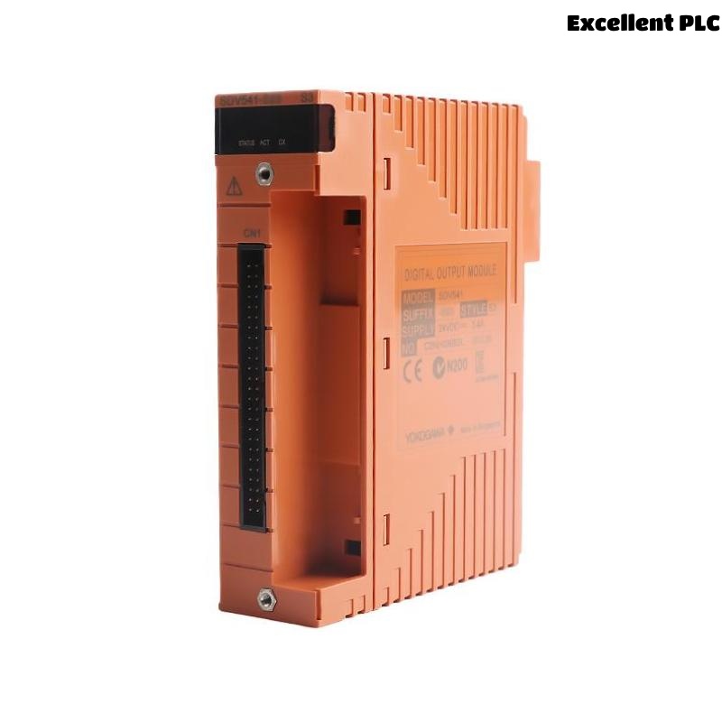
SDV541-S63/PRP Digital Output Module Overview
The Yokogawa SDV541-S63/PRP Digital Output Module provides 16 isolated digital output channels operating at 24VDC. The module supports industrial control applications requiring reliable signal transmission to solenoid valves, relays, contactors, and shutdown devices. :contentReference[oaicite:1]{index=1}
Role of the SDV541-S63/PRP in Control Systems
- Digital actuator control
- Shutdown signal activation
- Relay switching applications
- Motor starter control
- Safety output execution
Key Technical Specifications
- 16 digital output channels
- 24VDC output voltage
- 0.2A maximum per channel
- 3.2A maximum total load
- 30ms maximum response time
- Module isolation design
The module requires a 24VDC external power supply rated at 3.4A minimum. :contentReference[oaicite:2]{index=2}
Installation Planning Strategy
- Review output loading calculations
- Verify cabinet capacity
- Confirm power supply sizing
- Inspect field wiring routes
- Validate System Configuration
24VDC Power Supply Requirements
- 24VDC nominal voltage
- +20% / -10% tolerance
- Minimum 3.4A supply capacity
- Dedicated output power source
- Protection fuse coordination
Control Cabinet Preparation
- Provide adequate airflow
- Separate power and signal cables
- Install grounding bar
- Allow maintenance access
Pre-Installation Inspection
- Verify model number
- Inspect connector condition
- Check signal cable adapter
- Review project drawings
- Confirm terminal labeling
SDV541-S63/PRP Installation Guide
- Switch off cabinet power.
- Install the module in the designated slot.
- Secure the retaining mechanism.
- Connect signal cable adapter.
- Verify module alignment.
- Inspect mechanical integrity.
Digital Output Wiring Practices
- Use shielded industrial cables
- Verify output polarity
- Separate high-voltage circuits
- Confirm load resistance limits
- Label all output channels
Grounding and Shielding Requirements
- Single-point shield grounding
- Avoid ground loops
- Maintain shield continuity
- Verify cabinet bonding
SDV541-S63/PRP Setup Procedure
INSTALL MODULE
VERIFY POWER SUPPLY
CONNECT OUTPUT WIRING
LOAD SYSTEM CONFIGURATION
ACTIVATE OUTPUT TEST
SAVE PARAMETERS
System Configuration Validation
- Output channel mapping
- Logic assignment review
- Signal destination verification
- Address validation
- Database synchronization
Output Channel Testing
- Output ON/OFF simulation
- Relay activation test
- Voltage measurement
- Load current verification
- Alarm validation
Commissioning Workflow
- Verify hardware installation.
- Check output voltage.
- Validate control logic.
- Perform field device testing.
- Execute integrated startup tests.
Performance Verification
- Output response monitoring
- Current consumption review
- Signal integrity assessment
- Alarm monitoring
Maintenance Recommendations
- Inspect terminals quarterly
- Verify load current annually
- Review configuration backups
- Monitor output health trends
Real Commissioning Case
During commissioning of a petrochemical shutdown system, several field solenoids connected to an SDV541-S63/PRP failed to energize.
- Measured supply voltage: 24.3VDC
- Output current: 0A
- Module diagnostics: Normal
- Field status: Inactive
Engineers initially suspected a faulty Digital Output Module. Detailed investigation showed that the external power supply common return was incorrectly landed on the terminal strip.
After rewiring:
- Output voltage stabilized at 23.9VDC
- All 16 channels responded correctly
- Shutdown valves energized normally
- Commissioning completed successfully
We observed that field wiring mistakes often appear identical to output module failures during startup activities.
SDV541-S63/PRP Installation Guide FAQ
What external power supply is required for the SDV541-S63/PRP?
A 24VDC power supply with a minimum capacity of 3.4A is recommended. :contentReference[oaicite:3]{index=3}
How many output channels are available?
The module provides 16 isolated digital output channels. :contentReference[oaicite:4]{index=4}
Why should output loading be reviewed before Commissioning?
Exceeding current limits can cause unstable operation and unexpected output failures.
Summary: Successful SDV541-S63/PRP Installation, Setup, and Commissioning require proper 24VDC power design, correct field wiring, validated System Configuration, and comprehensive output channel testing.