

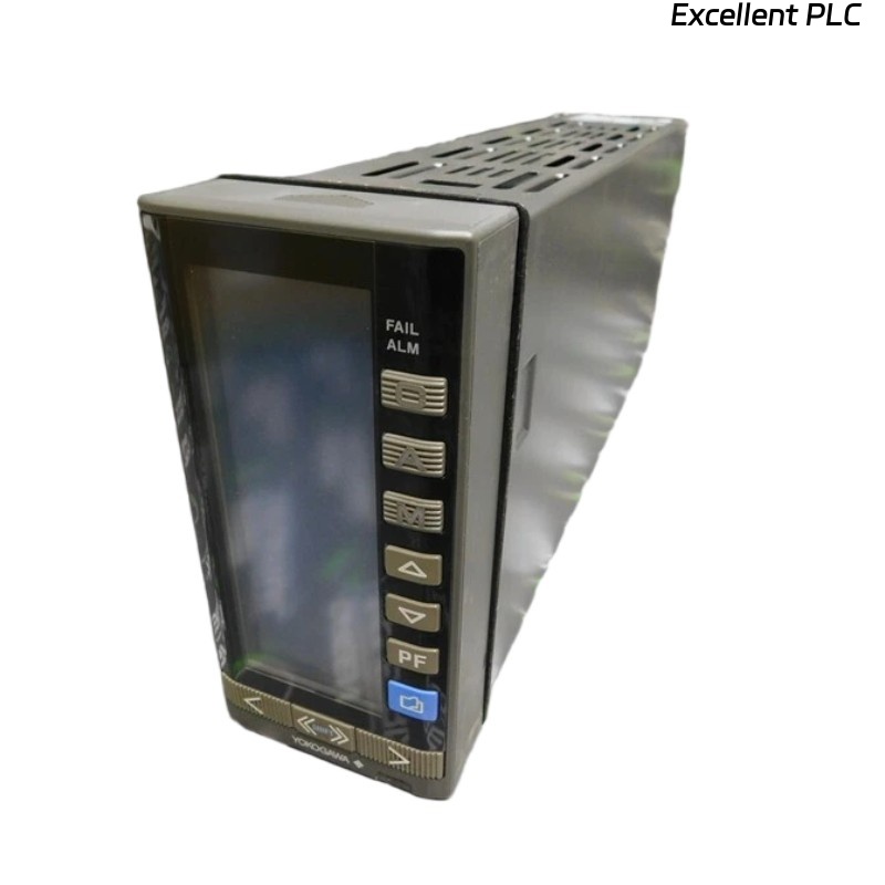
The Yokogawa YS170-012 S3 is a PLC-style programmable controller widely used for single-loop process control. Correct parameter configuration is critical to achieve stable control performance, accurate measurement, and reliable alarm handling.
This article provides a step-by-step engineering guide to configuring PID parameters, input/output ranges, and alarm settings, with practical logic examples for industrial applications.
1. Input Signal Configuration
Before any control logic is applied, the input signal must be correctly defined.
Typical Input Types:
-
4–20 mA
-
0–10 V
Configuration Steps:
-
Select input type in controller parameters
-
Define engineering unit range (e.g. °C, bar, %)
Scaling Logic
2. Output Signal Configuration
The output signal controls the final element (valve, VFD, heater).
Common Output Settings:
-
4–20 mA control output
-
Direct or reverse action
Output Limiting
3. PID Parameter Configuration
3.1 Understanding PID Parameters
-
P (Proportional): Response strength
-
I (Integral): Eliminates steady-state error
-
D (Derivative): Improves stability and response speed
3.2 PID Control Logic
Practical Tuning Tips:
-
Start with P-only control
-
Add I to eliminate offset
-
Use D only if process response is slow or oscillatory
4. Auto / Manual Mode Configuration
The YS170-012 S3 supports seamless switching between auto and manual modes.
Engineering Note: Always synchronize output values before switching to AUTO to avoid output jumps.
5. Alarm Parameter Configuration
Common Alarm Types:
-
High alarm (HH / H)
-
Low alarm (LL / L)
-
Deviation alarm
Alarm Logic Example
6. Engineering Best Practices
-
Verify scaling before enabling control
-
Tune PID under stable operating conditions
-
Use alarm delay to avoid nuisance alarms
-
Document all parameter settings for maintenance
Conclusion
Proper parameter configuration of the Yokogawa YS170-012 S3 is essential for achieving accurate measurement, stable PID control, and reliable alarm handling. By systematically configuring input/output ranges, carefully tuning PID parameters, and applying structured alarm logic, engineers can significantly improve system performance and operational reliability.
This guide provides a practical foundation for commissioning and maintaining YS170-012 S3 controllers in industrial environments.