

📘 1. Introduction
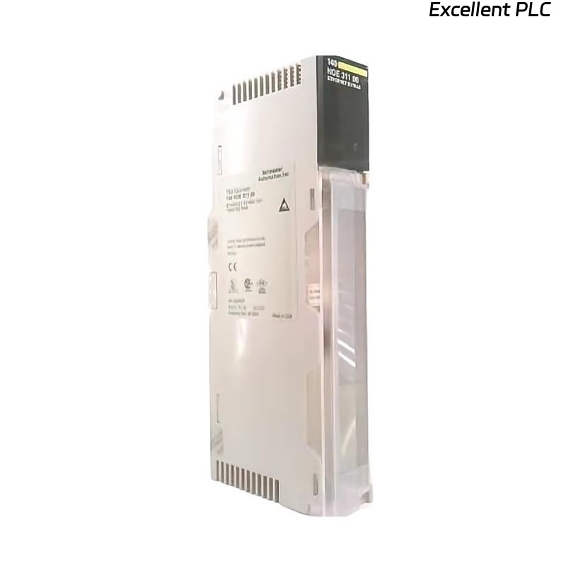
The Schneider 140NOE31100C is an Ethernet communication module for Modicon Quantum PLC systems.
It provides high-speed data exchange between the PLC and external devices such as HMIs, SCADA systems, and other Ethernet-enabled controllers.
This guide covers:
-
Physical installation in a Quantum PLC rack
-
Wiring and network connection
-
Software configuration in EcoStruxure Control Expert
-
Sample ladder logic code for basic communication test
⚙️ 2. Tools & Preparation
-
Anti-static wrist strap
-
Small flat-head screwdriver
-
Shielded CAT5e/CAT6 Ethernet cable
-
Laptop with EcoStruxure Control Expert
-
Industrial Ethernet switch for testing
-
Multimeter to verify backplane voltage
⚠️ Always disconnect the PLC power before module insertion.
🏗️ 3. Hardware Installation
Step 1 — Power Down the PLC
-
Turn off the main power supply to the PLC rack.
Step 2 — Module Mounting
-
Locate the slot for the 140NOE31100C module.
-
Align the module with the backplane guide rails.
-
Slide the module evenly until it clicks.
-
Secure it using the side locking screw.
⚠️ Avoid lateral force to prevent bent pins.
Step 3 — Ethernet Connection
-
Connect the RJ-45 port to your network switch.
-
Use shielded CAT5e/CAT6 cable to reduce interference.
-
Verify proper grounding.
🖥️ 4. Software Configuration
-
Open EcoStruxure Control Expert.
-
In the project, add the 140NOE31100C module in the corresponding slot.
-
Configure Ethernet settings:
-
Static IP: e.g., 192.168.1.50
-
Subnet Mask: 255.255.255.0
-
Gateway: 192.168.1.1 (if needed)
-
-
Enable Modbus TCP or Global Data as required.
-
Download configuration to PLC.
-
Confirm module recognized and RUN LED is green.
🔍 5. LED Indicators Reference
| LED | Color | Status | Meaning |
|---|---|---|---|
| RUN | Green | ON | Module initialized |
| ERR | Red | OFF | Normal |
| ERR | Red | ON | Hardware or configuration error |
| LINK | Green | ON | Ethernet link detected |
| ACT | Yellow | Flashing | Data transmission active |
🧩 6. Sample Running Code
Below is a basic ladder logic example for Modbus TCP communication using 140NOE31100C.
This code polls a remote device at IP 192.168.1.100 and reads register 40001 into PLC memory.
💡 Pro Tip: Replace
NOE31100C_Slot5with the actual module variable name in your project.
Always verify remote IP and register addresses before running code.
🔧 7. On-Site Verification
-
Confirm RUN LED is solid green.
-
Ping the module from your PC to verify network connectivity.
-
Observe LINK and ACT LEDs during ladder code execution.
-
Check Modbus TCP registers read correctly in PLC memory.
🧰 8. Troubleshooting Common Issues
| Symptom | Cause | Action |
|---|---|---|
| RUN LED off | Module not seated | Re-seat module |
| ERR LED on | Firmware mismatch | Update firmware |
| LINK LED off | Bad cable or switch port | Check cable, swap ports |
| Cannot read remote registers | IP mismatch or firewall | Verify IP, disable firewall temporarily |
| Intermittent communication | EMI interference | Use shielded cables, separate from high-power lines |
✅ 9. Final Verification Checklist
-
[✔] Module securely installed in rack
-
[✔] Ethernet cable connected and grounded
-
[✔] Module recognized in Control Expert
-
[✔] RUN LED green, ERR LED off
-
[✔] Ping test successful
-
[✔] Ladder logic communication test passed
After these steps, the 140NOE31100C module is fully operational and ready for industrial Ethernet communication.