

Table of Contents
- Bently Nevada 173688-01-20-12-5227 Installation Guide Entry
- Application Role of 3300 XL 8 mm Proximity Probe
- Installation Sequence Based on Machine Geometry
- Probe Gap Control and Linear Range Setup
- System Matching: Probe, Cable, and Proximitor
- Commissioning Verification Under Real Load
- FAQ
- Technical Summary
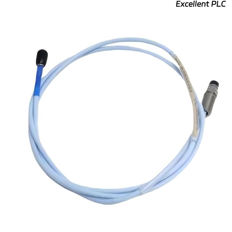
Bently Nevada 173688-01-20-12-5227 Installation Guide Entry
Bently Nevada 173688-01-20-12-5227 proximity probe installation failures are most often related to incorrect probe gap setup or system length mismatch, which results in inaccurate shaft vibration readings rather than sensor damage.
This Installation Guide focuses on engineering-based installation sequence and reliable signal acquisition.
Application Role of 3300 XL 8 mm Proximity Probe
- Non-contact measurement of shaft vibration and displacement
- Designed for rotating equipment such as turbines, compressors, and pumps
- Works as part of a calibrated transducer system
The probe uses eddy current principles to detect shaft movement with high precision. :contentReference[oaicite:0]{index=0}
Installation Sequence Based on Machine Geometry
- Confirm probe mounting location (radial or axial measurement)
- Verify shaft surface condition (clean, conductive, smooth)
- Install probe holder and adjust insertion depth
- Lock probe mechanically after final adjustment
Engineering Insight: Probe positioning must consider shaft runout and thermal expansion clearance.
IF signal fluctuates at startup:
    check probe mounting rigidity
    verify shaft alignment

IF no response:
    confirm probe facing correct surface
Probe Gap Control and Linear Range Setup
- Target gap voltage: -8V to -10V
- Represents center of linear measurement range
- Critical for accurate vibration amplitude detection
IF voltage > -5V:
    probe too far from shaft

IF voltage < -12V:
    probe too close to shaft
Field Note: Gap must be set under stable mechanical conditions (not during startup).
System Matching: Probe, Cable, and Proximitor
- Total system length must match calibration (e.g., 5m or 9m system)
- Connector type must match proximitor input
- Do not mix different probe series
Real Case:
During a turbine retrofit, vibration readings were consistently 30% lower than expected. Investigation showed probe matched with incorrect cable length (7m instead of calibrated 9m system). After replacing with correct cable, vibration increased from 2.8 mm/s to 4.1 mm/s, aligning with mechanical condition.
Commissioning Verification Under Real Load
- Measure gap voltage stability over time
- Check waveform consistency during load variation
- Compare with portable vibration analyzer
Commissioning ensures reliable integration into monitoring systems.
FAQ
Why is vibration reading inaccurate after installation?
This is usually due to incorrect system length or improper gap setting.
Can I reuse existing extension cables?
Only if they match the exact calibrated system length and type.
What happens if gap is not centered?
The probe operates outside its linear range, causing distorted signals.
Technical Summary
This Installation Guide shows that Bently Nevada 173688-01-20-12-5227 probe performance depends on precise gap control, correct system matching, and proper installation sequence. Accurate setup ensures stable and high-precision vibration monitoring.