 Excellent PLC


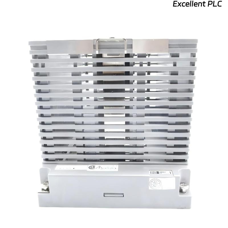
The Yokogawa AMN33 Communication Module Nest is a dedicated rack assembly used for installing communication modules in Yokogawa CENTUM CS 1000, CENTUM CS 3000, and CENTUM VP Distributed Control Systems (DCS). It provides mechanical support, backplane communication, power distribution, and interface connections for communication modules that exchange data with PLCs, analyzers, package units, intelligent instruments, and third-party automation systems. The AMN33 itself does not process communication data; all protocol handling is performed by the installed communication modules. Consequently, faults associated with the AMN33 rack may interrupt communication between the DCS and multiple external devices.
Contents
- 1. Understanding Communication Rack Faults
- 2. Common Failure Symptoms
- 3. Typical Causes
- 4. Initial Hardware Inspection
- 5. Communication Module Verification
- 6. Communication Cable Inspection
- 7. Diagnostic Analysis
- 8. Recommended Troubleshooting Workflow
- 9. Corrective Actions
- 10. Functional Recovery Verification
- 11. Preventive Maintenance
- 12. Industrial Maintenance Case
- 13. Frequently Asked Questions
Understanding Communication Rack Faults
The AMN33 functions as the hardware platform connecting Yokogawa communication modules to the DCS controller. Communication failures may originate from improper module installation, damaged backplane connectors, incorrect communication parameters, faulty serial cables, grounding problems, or failures of connected third-party equipment. Because several communication modules may share the same rack, one rack-level fault can affect multiple communication channels simultaneously.
Common Failure Symptoms
- Communication modules are not recognized by the controller.
- Serial communication stops unexpectedly.
- PLC or analyzer data cannot be updated.
- Frequent communication timeout alarms.
- CRC or checksum errors increase.
- Communication status LEDs indicate abnormal conditions.
- Multiple communication ports fail simultaneously.
- DCS reports communication hardware alarms.
Typical Causes
- Loose communication module installation.
- Damaged rack backplane connector.
- Faulty RS-232, RS-422, or RS-485 cable.
- Incorrect baud rate or communication parameters.
- Poor cable shielding or grounding.
- Connector oxidation or contamination.
- Rack power distribution fault.
- Internal AMN33 hardware failure.
- External device communication malfunction.
Initial Hardware Inspection
- Verify the AMN33 is securely mounted.
- Inspect communication module seating.
- Check backplane connectors.
- Inspect communication cable connectors.
- Verify rack power status.
- Inspect cabinet cooling and cleanliness.
Communication Module Verification
- Reseat communication modules.
- Verify module slot assignments.
- Inspect module diagnostic LEDs.
- Check communication protocol configuration.
- Verify controller recognition of each module.
- Review DCS diagnostic logs.
Communication Cable Inspection
- Inspect cable continuity.
- Verify connector pin assignments.
- Measure communication signal integrity.
- Confirm cable shielding.
- Inspect grounding connections.
- Verify termination resistors for RS-485 networks where applicable.
Diagnostic Analysis
| Observed Condition | Possible Diagnosis |
|---|---|
| All communication modules offline | Rack power or backplane communication failure |
| Single communication module unavailable | Improper module seating or module hardware fault |
| Repeated communication timeouts | Incorrect communication parameters or faulty cable |
| Frequent CRC errors | Electrical noise, grounding issue, or damaged cable |
| Multiple communication channels fail | Rack connector or shared power distribution problem |
Recommended Troubleshooting Workflow
CHECK DCS DIAGNOSTICS
VERIFY RACK POWER
CHECK MODULE INSTALLATION
VERIFY COMMUNICATION PARAMETERS
INSPECT SERIAL CABLES
TEST COMMUNICATION PORTS
VERIFY EXTERNAL DEVICE STATUS
CONFIRM SYSTEM RECOVERY
Corrective Actions
- Reseat communication modules.
- Replace damaged communication cables.
- Correct protocol configuration.
- Repair connector damage.
- Improve cable grounding and shielding.
- Restore rack power connections.
- Replace defective communication modules.
- Replace the AMN33 rack if internal hardware failure is confirmed.
Functional Recovery Verification
- Confirm all communication modules are detected.
- Verify successful communication with external equipment.
- Monitor communication error counters.
- Check protocol diagnostics.
- Verify stable long-term communication.
- Confirm all DCS alarms are cleared.
Preventive Maintenance
- Inspect module seating regularly.
- Clean communication connectors.
- Verify cable shielding integrity.
- Check communication parameter consistency.
- Inspect grounding systems.
- Review communication diagnostic history.
Industrial Maintenance Case
During operation of a chemical processing facility, communication between the Yokogawa DCS and several PLC-controlled package units suddenly became unstable. Multiple communication timeout alarms appeared simultaneously.
Inspection determined that a communication module installed in the AMN33 rack had become partially disengaged due to cabinet vibration. Maintenance personnel reseated the module, inspected the backplane connectors, tightened the mounting hardware, and verified RS-485 cable termination.
Following corrective maintenance:
- Communication with all PLCs resumed normally.
- Timeout alarms disappeared.
- Data exchange remained stable during extended operation.
- The communication network returned to normal service.
Frequently Asked Questions
Does the AMN33 handle communication protocols?
No. Communication protocols such as Modbus or serial data exchange are processed entirely by the installed communication modules. The AMN33 provides only the rack infrastructure and electrical interface.
Why can one rack fault interrupt several communication channels?
Because multiple communication modules share the same backplane, power supply, and rack connections, a single hardware problem can affect several communication interfaces simultaneously.
What should be checked before replacing the AMN33?
Verify rack power, module seating, backplane connectors, communication parameters, cable integrity, grounding, controller diagnostics, and the operating status of connected external equipment before concluding that the rack assembly has failed.
Summary
Effective troubleshooting of the Yokogawa AMN33 Communication Module Nest requires systematic inspection of rack power, module installation, communication cables, protocol configuration, grounding, and DCS diagnostics. Regular preventive maintenance ensures reliable communication between Yokogawa CENTUM Distributed Control Systems and connected industrial automation equipment.