 Excellent PLC


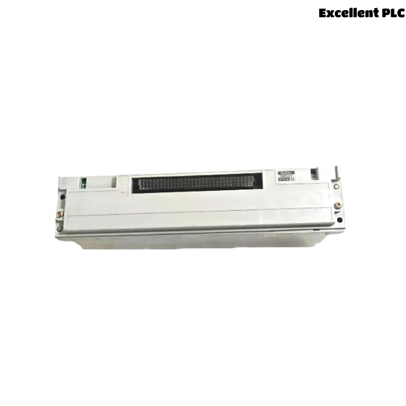
The Yokogawa AMM52T Control Card is a 4–20 mA analog output multiplexer module used in Yokogawa CENTUM CS / CENTUM VP Distributed Control Systems (DCS) and RIO systems. The module converts digital control commands from the controller into analog current output signals for field devices such as control valves, valve positioners, VFD references, and other final control elements. Because AMM52T directly affects process control actions, any output abnormality may cause valve position errors, unstable control loops, or process deviations. This guide provides a systematic troubleshooting method for diagnosing AMM52T output faults and restoring normal control operation.
Contents
- 1. Understanding Output Module Faults
- 2. Common Failure Symptoms
- 3. Typical Causes
- 4. Initial Hardware Inspection
- 5. Analog Output Signal Verification
- 6. Diagnostic Analysis
- 7. Recommended Troubleshooting Workflow
- 8. Corrective Actions
- 9. Functional Recovery Verification
- 10. Preventive Maintenance
- 11. Industrial Maintenance Case
- 12. Frequently Asked Questions
Understanding Output Module Faults
The AMM52T receives output commands from the DCS controller and generates proportional 4–20 mA current signals. A correct output requires proper controller configuration, healthy module hardware, correct loop wiring, suitable field device input impedance, and stable grounding. Output failures may originate from the DCS control logic, configuration errors, field wiring problems, actuator faults, or AMM52T internal circuitry.
Common Failure Symptoms
- Control valve does not move.
- Valve position does not match DCS command.
- Output current remains fixed.
- Output signal is zero mA.
- Output signal exceeds normal range.
- Multiple output channels fail.
- Output fluctuates unexpectedly.
- DCS reports analog output alarm.
Typical Causes
- Incorrect output channel configuration.
- Wrong loop polarity.
- Open output circuit.
- Damaged field cable.
- Faulty valve positioner or actuator.
- Incorrect scaling parameters.
- Grounding or shielding problems.
- AMM52T output circuit failure.
Initial Hardware Inspection
- Verify AMM52T installation status.
- Check module diagnostic indicators.
- Inspect output terminal connections.
- Verify field device wiring.
- Check actuator or positioner power supply.
- Inspect cabinet environment.
Analog Output Signal Verification
- Use a calibrated current meter to measure output.
- Force output value from DCS maintenance interface.
- Verify 4 mA output condition.
- Verify 12 mA mid-range output condition.
- Verify 20 mA full-scale output condition.
- Compare measured current with commanded value.
Diagnostic Analysis
| Observed Condition | Possible Diagnosis |
|---|---|
| Output = 0 mA | Open loop, wiring error, power loss, or module failure |
| Output fixed at one value | Configuration error or output channel fault |
| Valve movement incorrect | Scaling error, positioner fault, or calibration problem |
| Multiple outputs failed | Power supply issue or module hardware fault |
| Output unstable | Electrical interference or poor grounding |
Recommended Troubleshooting Workflow
CHECK DCS OUTPUT COMMAND
VERIFY AMM52T STATUS
CHECK CHANNEL CONFIGURATION
MEASURE OUTPUT CURRENT
INSPECT FIELD WIRING
CHECK ACTUATOR RESPONSE
VERIFY LOOP CALIBRATION
CONFIRM NORMAL CONTROL
Corrective Actions
- Correct output channel configuration.
- Repair open-loop wiring.
- Correct output polarity.
- Replace damaged signal cables.
- Calibrate valve positioners.
- Correct engineering scaling.
- Improve grounding and shielding.
- Replace AMM52T module if output hardware failure is confirmed.
Functional Recovery Verification
- Confirm output current follows DCS command.
- Verify field actuator response.
- Perform complete 4–20 mA loop test.
- Check control loop stability.
- Confirm all alarms are cleared.
Preventive Maintenance
- Perform periodic analog output calibration.
- Inspect output loop wiring.
- Verify actuator calibration.
- Review DCS diagnostic records.
- Check cabinet temperature and ventilation.
- Maintain proper grounding practices.
Industrial Maintenance Case
During operation of a refinery pressure control system, one control valve remained fully closed even though the DCS output command increased to 80%.
Troubleshooting found that the AMM52T output channel was producing the correct current signal, but the valve positioner input terminal had poor contact due to a loose field connection. After repairing the terminal connection and recalibrating the positioner:
- The valve responded correctly to DCS commands.
- The 4–20 mA loop matched expected values.
- Pressure control returned to normal.
- No further analog output alarms occurred.
Frequently Asked Questions
Why does AMM52T output show 0 mA?
Possible causes include open loop wiring, missing field device power, incorrect polarity, output channel configuration errors, or internal module failure.
Why is the measured output different from the DCS command?
Possible causes include incorrect scaling, calibration errors, wiring resistance, actuator input problems, or output channel malfunction.
What should be checked before replacing AMM52T?
Verify DCS output commands, channel configuration, loop wiring, field device power, actuator operation, grounding, and measured current output before replacing the module.
Summary
Effective troubleshooting of the Yokogawa AMM52T Control Card requires systematic verification of DCS commands, module diagnostics, output current measurement, field wiring, actuator response, grounding, and calibration. Proper maintenance and periodic loop testing ensure reliable analog control output and stable operation of Yokogawa CENTUM Distributed Control Systems.