

1. Product Overview and Technical Specifications
1.1 Module Description
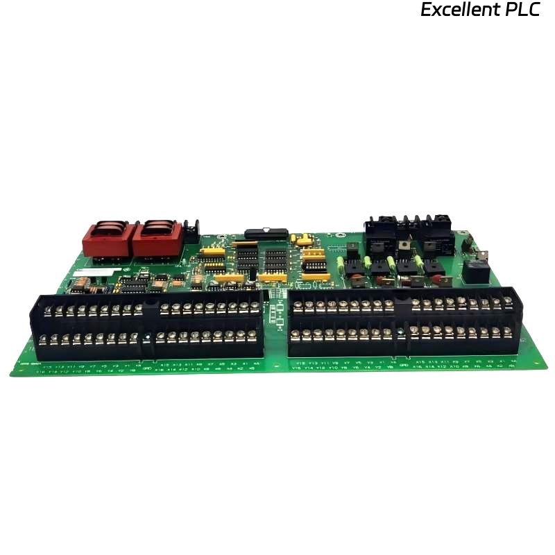
The ABB 07 AB 200 (Part No. GJV3072413R1) is a high-performance binary output module, typically used in ABB AC 800M or similar Distributed Control System (DCS) series. This module provides electrically isolated relay contact outputs to control field devices (e.g., valves, motor starters, alarms), converting control system logic into physical actions.
Key Features:
-
Output Type: Relay contact outputs (Normally Open/Normally Closed)
-
Number of Channels: 16 independently isolated outputs
-
Contact Rating: Typically 2A @ 230V AC
-
Load Voltage Range: 24V DC to 230V AC
-
Electrical Isolation: Channel-to-channel and channel-to-logic isolation
-
Diagnostics: Output status readback, short-circuit detection (on some models)
-
Communication Interface: Connects to controller via fieldbus (e.g., Profibus DP, Foundation Fieldbus)
1.2 Safety and Regulatory Information
⚠️ Read all safety instructions before installation.
-
Hazardous Voltage: Output terminals may be connected to hazardous voltages (up to 230V AC). Implement a full Lockout/Tagout (LOTO) procedure before working on the module or connected devices. Verify absence of voltage on both logic and field power circuits.
-
ESD Protection: The module contains electrostatic discharge (ESD) sensitive components. Always wear a grounded wrist strap and handle the module by its edges. Store and transport in anti-static packaging.
-
Environmental Limits: For installation in Pollution Degree 2 environments. Operating temperature: -20°C to +60°C. Relative humidity: 5% to 95% (non-condensing). Installation inside an IP-rated enclosure is required for protection against dust and moisture.
2. Pre-Installation Planning and Requirements
2.1 Tools and Materials Checklist
| Tool / Material | Specification / Requirement | Purpose |
|---|---|---|
| Torque Screwdriver | 0.6 N·m ±10% | For terminal and mounting screw tightening |
| Wire Stripper | Suitable for 0.5-2.5mm² wire | Preparing field wiring |
| Digital Multimeter | CAT III 600V minimum rating | Voltage verification and troubleshooting |
| Terminal Resistors (if needed) | Matched to fieldbus protocol (e.g., 220Ω for Profibus DP) | Bus termination |
| DIN Rail | 35mm standard top-hat rail | Module mounting base |
| Label Printer | Industrial grade | Wire and terminal identification |
2.2 System Compatibility and Configuration Check
Before physical installation, confirm the system is ready:
-
Controller Compatibility:
-
Verify the controller firmware supports this I/O module.
-
Check available backplane slot and power supply capacity.
-
Confirm the communication protocol and address settings.
-
-
Software Preparation:
-
Install the latest version of Control Builder or relevant engineering tool.
-
Download the correct Device Description File (GSD for Profibus, EDD for others).
-
Have the module configuration file prepared.
-
-
Site Verification:
-
Ensure sufficient space for installation (allow minimum 50mm on each side for ventilation).
-
Confirm the DIN rail is securely mounted and properly grounded.
-
Ambient temperature must be within specified operating range.
-
3. Step-by-Step Installation Procedure
3.1 Mechanical Mounting
Step 1: Prepare DIN Rail
-
Ensure the DIN rail is properly bonded to the panel ground (grounding resistance <0.1Ω is recommended).
-
Mark the position for the module, maintaining required clearance from other heat-producing components.
Step 2: Mount the Module
1.  Remove the module from its anti-static packaging, handling by the edges only.
2.  Hook the top recess of the module onto the upper lip of the DIN rail.
3.  Press the module downward until the bottom locking clip snaps securely into place on the rail (audible 'click').
4.  Secure the module using the fixing screw at the bottom. **Tighten to 0.6 N·m.**
5.  Connect the functional earth wire (if provided) to the designated PE terminal.
Step 3: Establish Bus Communication
1.  Use approved, shielded fieldbus cable.
2.  Connect the bus cable according to network topology:
    - First module: Connect from controller port to module 'IN' port.
    - Middle modules: Connect from previous module's 'OUT' to this module's 'IN'.
    - Last module: Install the terminating resistor at the 'OUT' port (if required by protocol).
3.  Ensure connectors are fully inserted and latched. Dress cables neatly to avoid strain.
3.2 Electrical Wiring for Field Devices
Example: Wiring Channel 1 to a 24V DC Solenoid Valve
Terminal Designation (Typical):
1L+   : Field Power Positive (24V DC)
1M    : Field Power Negative / Common
1Q1   : Channel 1 Output Contact (Normally Open)
1Q2   : Channel 1 Output Contact (Normally Closed) - if available

Wiring Procedure:
1.  ISOLATE and VERIFY ZERO VOLTAGE on the field power supply.
2.  Connect the 24V DC field supply to terminals 1L+ and 1M.
3.  Connect the load (e.g., solenoid valve):
    - For NO operation: Connect one wire of the load to 1Q1, the other to 1M.
    - For NC operation: Connect one wire of the load to 1L+, the other to 1Q2.
4.  Use appropriate wire gauge (min. 0.5mm² / 20 AWG, max. 2.5mm² / 14 AWG).
5.  Tighten terminal screws to **0.5-0.6 N·m**. Do not overtighten.
6.  Apply permanent, legible labels to all wires.
Critical Wiring Practices:
-
Separation: Route power cables (feeding loads) and communication/control cables in separate trays or with a minimum 150mm spacing.
-
Shielding: For analog or communication signals, use shielded cables. Ground the shield at ONE END ONLY (typically at the system ground bar) to avoid ground loops.
-
Load Protection: For inductive loads (relays, contactors, solenoids), install protective devices:
-
DC Loads: Install a flyback diode (e.g., 1N4007) in reverse parallel across the load.
-
AC Loads: Install an RC snubber circuit (e.g., 100Ω + 0.1µF) or a metal oxide varistor (MOV) across the load.
-
4. Software Configuration and Commissioning
4.1 Hardware Configuration in Engineering Software
Step 1: Add Module to Hardware Tree
In ABB Control Builder:
-
Open your project and navigate to the Hardware Configuration view.
-
From the hardware catalog, browse to:
-
Manufacturer: ABB
-
Product Family: I/O Modules or Fieldbus Peripherals
-
Specific Type: 07 AB 200 or search by article number GJV3072413R1.
-
-
Drag and drop the module to the appropriate slot or position in your fieldbus station layout.
Step 2: Configure Module and Channel Parameters
-
Module Parameters:
-
Node Address: Must match the physical address set on the module (if any) or the station number in the bus configurator.
-
Watchdog Time: Set the communication watchdog timer (default is often 1000ms).
-
Fault State Behavior: Define the safe state for all outputs upon communication failure (e.g., “Hold last value” or “Switch to OFF“).
-
-
Channel Parameters (per channel):
-
Output Type: Select “Steady” for maintained output or “Pulse” for timed output.
-
Pulse Width: Configurable if “Pulse” type is selected.
-
Startup Value: Define the state of the output when the controller transitions from STOP to RUN.
-
Diagnostics: Enable/disable short-circuit or open-load detection if supported.
-
4.2 Logic Programming Example
Here is a basic example in Structured Text (ST) for controlling a pump with start/stop and interlock.
(* Motor Control Function Block *)
FUNCTION_BLOCK PumpControl
VAR_INPUT
    AutoStart    : BOOL; // Auto start command from process
    ManualStart  : BOOL; // Manual start from HMI
    StopCmd      : BOOL; // Stop command (HMI or process)
    PressureHigh : BOOL; // Interlock: Pump run allowed if NOT high
    MaintenanceMode : BOOL; // Disables auto start
END_VAR
VAR_OUTPUT
    PumpRunCmd   : BOOL; // Command to physical output
    StatusReady  : BOOL; // Status feedback to HMI
END_VAR

(* Control Logic *)
StatusReady := NOT MaintenanceMode AND NOT PressureHigh;
PumpRunCmd := ( (AutoStart AND NOT MaintenanceMode) OR ManualStart )
              AND NOT StopCmd
              AND StatusReady;

(* In the main program *)
PROGRAM Main_PLC
VAR
    Pump1 : PumpControl;
END_VAR

// Assign inputs
Pump1.AutoStart := Process_StartSignal;
Pump1.ManualStart := HMI_Start_PB;
Pump1.StopCmd := HMI_Stop_PB OR EmergencyStop_PB;
Pump1.PressureHigh := PressureSwitch;
Pump1.MaintenanceMode := HMI_MaintMode;

// Map the output to a physical channel
// Assumes 'DO_Channel01' is a variable linked to hardware output channel 1
DO_Channel01 := Pump1.PumpRunCmd;
4.3 Systematic Commissioning and Testing
Final Pre-Power Check:
□ All power connections are correct and polarized.
□ All terminal screws are tightened to specified torque.
□ Unused channels or terminals are not touching.
□ Module is firmly secured to the DIN rail.
□ Cable shields are properly grounded (single point).
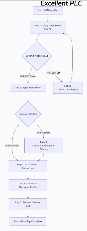
Sequential Power-Up and Test Procedure:
Channel Test Record Table:
| Channel | Test Command (Force) | Expected Action (Field Device) | Actual Result | Pass/Fail | Remarks |
|---|---|---|---|---|---|
| 1 | ON | Pump contactor engages | Contactor engaged | ✓ | |
| 2 | ON | Red alarm beacon lights | Beacon illuminated | ✓ | |
| 3 | ON | Valve opens | No movement | ✗ | Check valve power supply |
| … | … | … | … | … | … |
5. Diagnostics, Troubleshooting, and Maintenance
5.1 Interpreting Status LEDs
| LED | Color | State | Meaning | Recommended Action |
|---|---|---|---|---|
| PWR | Green | Steady ON | Logic power OK | – |
| PWR | Off | – | No logic power | Check 24V DC supply, fuses, wiring. |
| RUN | Green | Steady ON | Operating normally, communication OK | – |
| RUN | Green | Flashing | Running, but no valid configuration | Download hardware configuration to module. |
| RUN | Red | Flashing | Bus communication fault | Check node address, bus cabling, termination, and controller connection. |
| ERR/INTF | Red | Steady ON | Module internal error | Cycle power. If persistent, replace module. Check for overheating. |
| CHx (per channel) | Green | Steady ON | Channel is active (output energized) | – |
| CHx (per channel) | Red | Flashing | Channel fault (e.g., short circuit, overload) | Disconnect load and check resistance. Verify load rating vs. module capability. |
5.2 Common Fault Scenarios and Solutions
Scenario 1: Module not recognized by controller.
-
Possible Causes: Incorrect GSD/EDD file, wrong node address, bus cable fault, defective module.
-
Troubleshooting Steps: Verify the device description file is installed. Check the physical node address (DIP switches if present) matches the software configuration. Use a bus analyzer to check signal integrity on the cable. Try the module on a known-good station.
Scenario 2: Specific output channel does not operate.
-
Possible Causes: Faulty field device/wiring, channel not configured/forced in software, internal relay failure, fuse blown (if module has fuses).
-
Troubleshooting Steps: First, use the engineering software to force the output ON. Measure voltage directly at the output terminal (between Qx and M). If voltage is present, the fault is in the field wiring or device. If no voltage, check the channel’s configuration (e.g., is it inhibited?) and verify the module’s internal diagnostics.
Scenario 3: Erratic operation or module resets.
-
Possible Causes: Insufficient power supply (high current draw), poor grounding, electrical noise, overheating.
-
Troubleshooting Steps: Measure the voltage at the module’s power terminals during operation; it must stay within 24V DC ±10%. Calculate the total current draw of all connected loads. Ensure the cabinet cooling is functional and the ambient temperature is within limits.
5.3 Preventive Maintenance Schedule
| Task | Frequency | Procedure |
|---|---|---|
| Visual Inspection | Weekly | Check all status LEDs for normal indication. Listen for audible buzzing from relays. |
| Thermal Inspection | Quarterly | Use an IR thermometer to check module temperature. It should not exceed 60°C. |
| Mechanical Check | Bi-Annually | Verify all terminal screws and mounting screws are tight. Check for dust buildup on vents. |
| Electrical Verification | Annually | Measure field supply voltage stability. Perform a full functional test of all channels. |
| Firmware/Config Backup | After any change | Always archive the complete hardware and application configuration after modifications. |
6. Technical Data Summary
Electrical Specifications:
-
Supply Voltage (Logic): 24V DC (19.2 – 28.8V)
-
Power Consumption: Typically 2.5W (base module, excluding load current)
-
Isolation Test Voltage: 500V AC between channels, 1500V AC between channel and logic.
-
Switching Time: Turn-on delay <1ms, Turn-off delay <10ms (resistive load).
-
Maximum Switching Frequency: 10 Hz (resistive load).
Mechanical & Environmental Data:
-
Dimensions (W x H x D): Approx. 25mm x 100mm x 75mm
-
Weight: Approx. 200g
-
Degree of Protection: IP20 (for installation inside a protective enclosure).
-
Standards Compliance: Conforms to IEC 61326-3-1 for EMC immunity in industrial environments.