

Table of Contents
- Bently Nevada 170180-01-00 Troubleshooting Entry
- Typical Sensor Input Fault Patterns
- Fault Diagnosis Logic for I/O Modules
- Common Causes of Transducer Input Failure
- Real Case: Mixed Sensor Configuration Fault
- Recovery Strategy and System Stabilization
- FAQ
- Technical Summary
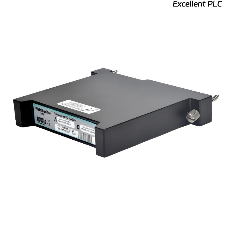
Bently Nevada 170180-01-00 Troubleshooting Entry
Bently Nevada 170180-01-00 external transducer I/O module troubleshooting shows that signal loss or abnormal readings are primarily caused by sensor wiring errors, incorrect configuration, or power supply instability rather than module failure.
This guide provides a structured fault diagnosis approach based on signal characteristics and system configuration.
Typical Sensor Input Fault Patterns
- No signal on one or both channels
- Incorrect or scaled readings
- High noise or fluctuating signals
- Intermittent signal loss
Understanding patterns helps isolate issues quickly.
Fault Diagnosis Logic for I/O Modules
IF no signal:
    check sensor power
    verify wiring continuity

IF incorrect readings:
    check sensor type configuration
    verify scaling parameters

IF noisy signal:
    inspect grounding
    check cable routing

IF intermittent signal:
    inspect connectors
    verify terminal tightness
This logic reduces unnecessary module replacement.
Common Causes of Transducer Input Failure
- Incorrect sensor wiring (proximitor vs accelerometer)
- Power supply instability
- Improper grounding or shielding
- Loose or corroded terminals
Real Case: Mixed Sensor Configuration Fault
In a gas compressor system, Channel A showed stable readings while Channel B displayed erratic values.
Observed Data:
- Channel A: 3.5 mm/s stable
- Channel B: fluctuating 0–10 mm/s
Analysis: Accelerometer connected to proximitor-configured channel.
Root Cause: Sensor type mismatch with channel configuration.
Solution:
- Reconfigured input type for Channel B
- Adjusted scaling parameters
Result: Channel B stabilized at 3.8 mm/s.
Recovery Strategy and System Stabilization
- Standardize sensor type configuration
- Verify wiring and terminal connections
- Ensure stable power supply
- Improve grounding and shielding practices
Systematic troubleshooting ensures stable signal acquisition.
FAQ
Why is there no signal on one channel?
This is often caused by wiring errors or missing sensor power.
How to identify sensor mismatch?
Compare sensor type with channel configuration and signal characteristics.
Is module failure common?
No, most issues are related to wiring and configuration.
Technical Summary
This Troubleshooting Guide demonstrates that Bently Nevada 170180-01-00 module faults are mainly caused by incorrect system configuration and installation issues. A structured fault diagnosis approach ensures reliable monitoring system performance.