

Table of Contents
- Bently Nevada 170133-XXX-00 Troubleshooting Entry
- Signal Fault Patterns in Dual Proximitor Modules
- Fault Diagnosis Framework Based on System Length
- Common Causes of Proximitor Module Faults
- Real Case: Mixed System Length Failure
- Optimization Strategy for Stable Operation
- FAQ
- Technical Summary
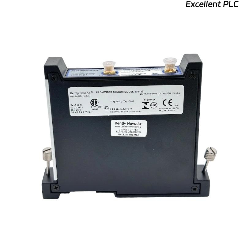
Bently Nevada 170133-XXX-00 Troubleshooting Entry
Bently Nevada 170133-XXX-00 dual proximitor module troubleshooting reveals that most faults—such as abnormal voltage output, signal distortion, or channel inconsistency—are caused by system length mismatch, incorrect probe gap, or wiring issues rather than module failure.
This guide focuses on diagnosing faults based on system configuration behavior.
Signal Fault Patterns in Dual Proximitor Modules
- Output voltage not centered around -9V
- Nonlinear signal response
- Channel A and B showing different trends
- Signal saturation at high or low limits
These patterns indicate configuration-related faults.
Fault Diagnosis Framework Based on System Length
IF voltage too high (-2V to -5V):
    suspect incorrect system length
    verify XXX code vs actual probe system

IF voltage too low (-12V to -17V):
    check probe gap too small
    inspect probe positioning

IF channels inconsistent:
    compare both probe systems
    verify identical length and calibration

IF signal nonlinear:
    inspect probe and cable integrity
    verify system configuration
This framework prioritizes configuration validation before hardware replacement.
Common Causes of Proximitor Module Faults
- Mismatch between XXX option and actual probe system length
- Improper probe gap adjustment
- Cable damage or incorrect connection
- Incorrect rack installation affecting backplane contact
Real Case: Mixed System Length Failure
In a compressor monitoring system, Channel A used a 9m probe system while Channel B used a 5m system on a 170133-090-00 module.
Observed Data:
- Channel A voltage: -9.1V (stable)
- Channel B voltage: -4.5V (unstable)
Root Cause: System length mismatch between channels.
Solution:
- Replaced Channel B cable to match 9m system
- Recalibrated probe gap
Result: Both channels stabilized at -9V baseline with consistent vibration readings.
Optimization Strategy for Stable Operation
- Standardize probe system length across channels
- Maintain correct probe gap voltage
- Perform regular signal validation checks
- Ensure proper installation and wiring integrity
System-level optimization reduces long-term faults.
FAQ
Why is the signal voltage abnormal?
This is often caused by mismatch between system length and module calibration.
How to identify system length issues?
Compare actual probe + cable length with module XXX specification.
Is module replacement required for signal faults?
No, most issues are configuration-related rather than hardware failure.
Technical Summary
This Troubleshooting Guide demonstrates that Bently Nevada 170133-XXX-00 module faults are primarily caused by system configuration errors, especially system length mismatch. A structured fault diagnosis approach ensures accurate and reliable vibration monitoring.