

Table of Contents
- Bently Nevada 173687-02-10-11-05 Installation Guide Entry
- Working Principle of 3300 XL 8 mm Proximity Probe
- Probe Mounting Strategy and Gap Positioning
- Extension Cable and Proximitor Matching
- Critical Installation Risks in Field Conditions
- Signal Validation and Commissioning
- FAQ
- Technical Summary
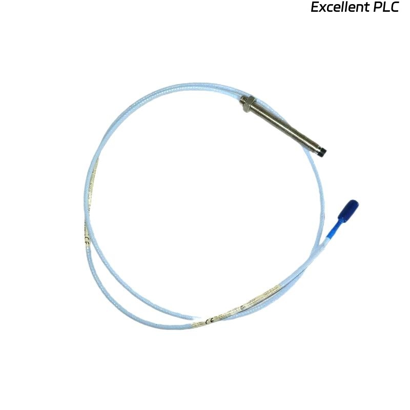
Bently Nevada 173687-02-10-11-05 Installation Guide Entry
Bently Nevada 173687-02-10-11-05 proximity probe installation errors are most often caused by incorrect probe gap positioning or mismatched cable system length, resulting in nonlinear vibration signals rather than probe failure.
This Installation Guide focuses on precise probe positioning, system matching, and vibration signal integrity.
Working Principle of 3300 XL 8 mm Proximity Probe
- Based on eddy current measurement principle
- Detects shaft displacement and vibration
- Requires conductive target surface
Typical system includes probe + extension cable + proximitor. :contentReference[oaicite:0]{index=0}
Engineering Insight: The probe must operate within its linear range to ensure accurate measurement.
Probe Mounting Strategy and Gap Positioning
- Install probe perpendicular to shaft surface
- Ensure target surface is clean and conductive
- Adjust gap voltage to -8V to -10V range
- Lock probe position to prevent drift
IF voltage > -5V:
    probe too far from shaft

IF voltage < -12V:
    probe too close

IF unstable signal:
    check mounting rigidity
Field Insight: Incorrect probe alignment (angled mounting) causes waveform distortion even when voltage appears normal.
Extension Cable and Proximitor Matching
- Total system length must match calibration (e.g., 5m / 9m)
- Use compatible 3300 XL proximitor modules
- Avoid mixing legacy and XL components
Mismatch causes scaling errors and unstable signals.
Real Experience: Engineers emphasize that probe, cable, and proximitor must match as a system and are not interchangeable. :contentReference[oaicite:1]{index=1}
Critical Installation Risks in Field Conditions
- Probe reading mounting bracket instead of shaft
- Loose probe threads due to vibration
- Improper shielding causing EMI noise
Real Case:
In a steam turbine installation, vibration readings remained near zero despite shaft rotation. Inspection revealed probe tip aligned with mounting sleeve instead of shaft. After repositioning, signal increased from 0.2 mm/s to 6.8 mm/s.
Signal Validation and Commissioning
- Verify baseline voltage (~ -9V typical)
- Check waveform stability during startup
- Compare readings with portable vibration analyzer
Proper commissioning ensures reliable machine protection.
FAQ
Why is the vibration reading very low?
This is usually caused by incorrect probe positioning or wrong target surface.
Can different cable lengths be used?
No, the system must match the calibrated length for accurate readings.
What is the correct gap voltage?
Typically between -8V and -10V for optimal linear range.
Technical Summary
This Installation Guide highlights that Bently Nevada 173687-02-10-11-05 probe performance depends on correct gap setting, precise mounting, and proper system matching. Accurate installation ensures reliable shaft vibration monitoring in critical machinery.