

Table of Contents
- Bently Nevada 177230-01-01-RU Installation Guide Entry
- Function of 177230 Seismic Sensor in Monitoring Systems
- Mounting Strategy Based on Vibration Energy Transfer
- 4–20 mA Loop Setup and System Configuration
- Typical Installation Failures and Field Insights
- Commissioning and Signal Verification
- FAQ
- Technical Summary
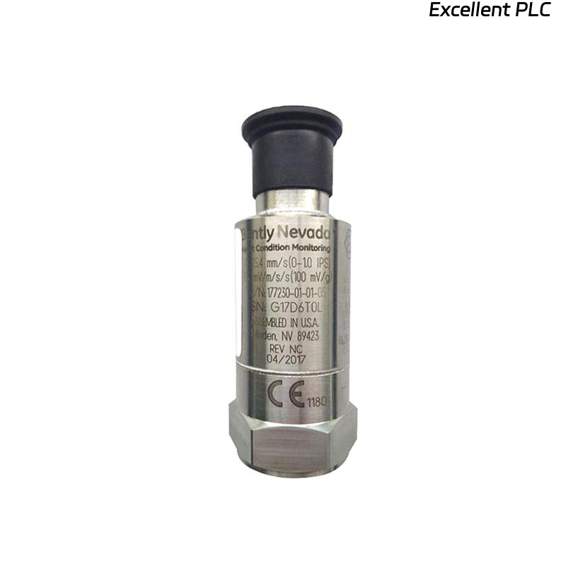
Bently Nevada 177230-01-01-RU Installation Guide Entry
Bently Nevada 177230-01-01-RU seismic sensor installation issues are most commonly caused by poor mechanical coupling or incorrect current loop wiring, leading to low or unstable vibration signals rather than transmitter failure.
This Installation Guide focuses on ensuring accurate vibration transmission and stable 4–20 mA signal output into PLC or monitoring systems.
Function of 177230 Seismic Sensor in Monitoring Systems
- Measures casing vibration (velocity, mm/s)
- Provides loop-powered 4–20 mA output
- Interfaces directly with PLC or I/O modules
The 177230-01-01-RU supports a measurement range up to 25.4 mm/s and frequency response from 10 Hz to 1 kHz, suitable for most rotating equipment monitoring. :contentReference[oaicite:0]{index=0}
Mounting Strategy Based on Vibration Energy Transfer
Installation must be treated as a vibration transmission system rather than a simple mounting task:
- Select rigid structure (bearing housing preferred)
- Ensure clean metallic contact surface
- Use 1/4-28 UNF threaded mounting hole
- Apply proper torque to ensure tight coupling
IF vibration signal weak:
    energy loss at mounting interface

IF signal unstable:
    check mounting tightness
Engineering Insight: Even small air gaps or paint layers can reduce vibration transmission significantly.
4–20 mA Loop Setup and System Configuration
- Typical power supply: 12–48 VDC
- Output: 4–20 mA proportional to vibration velocity
- Direct integration with PLC analog input
IF no current:
    check loop wiring
    verify supply voltage

IF signal fixed at 4 mA:
    no vibration detected or wiring issue

IF signal noisy:
    inspect grounding and shielding
Stable loop configuration ensures accurate data transmission.
Typical Installation Failures and Field Insights
- Mounting on flexible structures (covers, brackets)
- Improper grounding causing signal noise
- Cable routed alongside power cables
Real Case:
In a gas compressor unit, vibration readings stayed at 4–6 mA during operation.
Observed:
- No response during load increase
Root Cause: Sensor mounted on thin inspection plate.
Solution:
- Reinstalled on bearing housing
Result: Signal increased to 9–13 mA, matching actual vibration (~5 mm/s).
Commissioning and Signal Verification
- Verify baseline (~4–6 mA under low vibration)
- Monitor signal during startup
- Compare with handheld vibration analyzer
Commissioning ensures correct installation and reliable monitoring.
FAQ
Why is the signal always near 4 mA?
This indicates poor vibration transmission or incorrect installation location.
What is the correct mounting thread?
Standard 1/4-28 UNF mounting thread is used.
Can this sensor be used directly with PLC?
Yes, it outputs standard 4–20 mA signal compatible with PLC systems.
Technical Summary
This Installation Guide highlights that Bently Nevada 177230-01-01-RU performance depends on proper mechanical coupling, correct loop configuration, and stable installation conditions. Accurate setup ensures reliable vibration monitoring in industrial systems.