

Table of Contents
- Bently Nevada 177230-02 Installation Guide Entry
- 177230-02 Seismic Sensor Role in High-Vibration Systems
- Mechanical Installation Design for High Energy Vibration
- 4–20 mA Loop Setup and PLC System Configuration
- Engineering Risks Specific to High-Range Sensors
- Commissioning and Validation Procedure
- FAQ
- Technical Summary
Bently Nevada 177230-02 Installation Guide Entry
Bently Nevada 177230-02 seismic sensor installation failures are typically caused by improper mounting for high vibration range applications or incorrect system scaling, leading to signal compression rather than actual sensor malfunction.
This Installation Guide focuses on high-range vibration environments where accurate energy transfer and proper system configuration are critical.
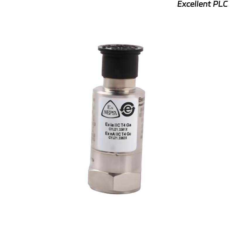
177230-02 Seismic Sensor Role in High-Vibration Systems
The 177230-02 seismic sensor is designed for high-range vibration monitoring:
- Measurement range up to 50.8 mm/s (2.0 in/s)
- Loop-powered 4–20 mA output
- Designed for PLC, DCS, and machinery protection systems
It is widely used in compressors, turbines, and heavy-duty rotating equipment where vibration amplitude is significantly higher than standard applications. :contentReference[oaicite:0]{index=0}
Mechanical Installation Design for High Energy Vibration
Unlike low-range sensors, high-range models require optimized installation for full vibration capture:
- Mount directly on bearing housing or rigid structure
- Remove paint or corrosion from mounting surface
- Use 1/4-28 UNF threaded connection
- Apply correct torque to avoid micro-slippage
IF vibration amplitude underestimated:
    check surface preparation
    verify mounting rigidity

IF signal clipped:
    check installation location vs vibration peak zone
Engineering Insight: At high vibration levels, even slight looseness can introduce damping errors greater than 20%.
4–20 mA Loop Setup and PLC System Configuration
- Supply voltage: 12–30 VDC typical
- Output: 4–20 mA proportional to vibration velocity
- Integration: PLC analog input or I/O module
IF output saturates early:
    PLC scaling mismatch

IF no signal:
    check loop continuity

IF unstable signal:
    inspect grounding and shielding
The sensor is loop-powered with simple installation and no field configuration required, making it suitable for rapid deployment. :contentReference[oaicite:1]{index=1}
Engineering Risks Specific to High-Range Sensors
- Incorrect PLC scaling (low-range configuration used)
- Mounting in low-vibration zones leading to under-reporting
- Mechanical resonance affecting measurement accuracy
Real Case:
In a steam turbine system, vibration readings plateaued at 12 mA despite increasing load.
Observed Data:
- Expected vibration >25 mm/s
- Signal did not exceed mid-range
Root Cause: PLC configured for 0–12.7 mm/s instead of 0–50.8 mm/s.
Solution:
- Updated PLC scaling to match sensor range
Result: Signal expanded to full range (6–18 mA), accurately reflecting machine condition.
Commissioning and Validation Procedure
- Check baseline output (~4–6 mA)
- Monitor signal across load changes
- Compare with portable vibration analyzer
Commissioning Tip: Always validate both mechanical installation and PLC scaling together.
FAQ
Why does the signal not reach 20 mA?
This is usually due to incorrect PLC scaling or insufficient vibration at the mounting point.
What is the measurement range of this sensor?
Up to 50.8 mm/s, suitable for high-vibration machinery. :contentReference[oaicite:2]{index=2}
Can it be used directly with PLC systems?
Yes, it outputs a standard 4–20 mA signal compatible with most PLC analog inputs.
Technical Summary
This Installation Guide shows that Bently Nevada 177230-02 performance depends on proper mechanical coupling, correct scaling configuration, and stable loop wiring. High-range applications require precise installation to ensure accurate vibration monitoring and reliable machinery protection.