

Table of Contents
- 21000-00-00-00-035-04-02 Installation Overview
- 3300XL Probe Housing Role in System Configuration
- Pre-Installation Checks and Risk Points
- Probe Housing Mechanical Installation Strategy
- Probe Gap Setup and Calibration Method
- Signal Chain Integration (Probe → Cable → Proximitor)
- Commissioning and Dynamic Verification
- Real Commissioning Case
- Installation FAQ
- Final Engineering Summary
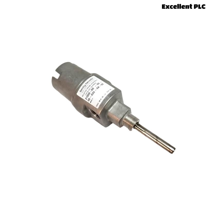
21000-00-00-00-035-04-02 Installation Overview
Bently Nevada 21000-00-00-00-035-04-02 proximity probe housing installation errors most commonly result in nonlinear shaft displacement signals. In many commissioning cases, improper gap setup leads to distorted vibration waveforms even though the probe and proximitor are functioning correctly.
This Installation Guide focuses on precision alignment, correct gap calibration, and full signal chain Setup to ensure accurate shaft monitoring.
3300XL Probe Housing Role in System Configuration
- Provides stable mechanical positioning for proximity probe
- Ensures consistent probe-to-shaft gap under thermal expansion
- Supports accurate eddy current signal measurement
- Critical part of the full monitoring chain (Probe + Extension Cable + Proximitor)
Pre-Installation Checks and Risk Points
- Verify shaft surface material and finish (conductive & smooth)
- Check available installation depth and clearance
- Confirm correct probe length and housing specification
- Ensure no mechanical interference during shaft rotation
Probe Housing Mechanical Installation Strategy
- Install housing perpendicular to shaft centerline
- Use rigid mounting point on machine casing
- Avoid thread misalignment during installation
- Secure housing to prevent vibration loosening
  // Installation Geometry Check
  IF Probe_Angle != 90deg THEN
      Signal_Linearity = FALSE;
  ELSE
      Measurement_Valid = TRUE;
  END_IF;
Probe Gap Setup and Calibration Method
- Adjust probe position slowly while monitoring gap voltage
- Target operating range: -8V to -10V DC
- Avoid extreme ends of probe linear range
- Lock position after calibration
Signal Chain Integration (Probe → Cable → Proximitor)
- Use matched 3300XL extension cable length
- Ensure connectors are clean and properly tightened
- Route cable away from high-power equipment
- Maintain consistent grounding strategy
Commissioning and Dynamic Verification
- Measure static gap voltage (-9V typical)
- Observe waveform during slow roll
- Verify stable displacement trend
- Check repeatability across operating speeds
Real Commissioning Case
In a gas turbine system, vibration readings were inconsistent across channels:
- Channel A: stable
- Channel B: distorted waveform
We observed that Channel B probe housing was slightly tilted (~5° off perpendicular).
After correction:
- Reinstalled housing with proper alignment
- Adjusted gap to -9.1V
Result:
- Waveform symmetry restored
- Measurement consistency achieved
Installation FAQ
What happens if the probe is not perpendicular to the shaft?
It causes nonlinear signal output and inaccurate displacement readings.
How precise should the gap voltage be?
It should stay within -8V to -10V for optimal linear performance.
Can I reuse old extension cables?
Only if they match the required system length and are in good condition.
Final Engineering Summary
The Bently Nevada 21000-00-00-00-035-04-02 Installation Guide shows that precision in alignment and gap setup is critical. Proper System Configuration ensures accurate and stable shaft vibration monitoring.