

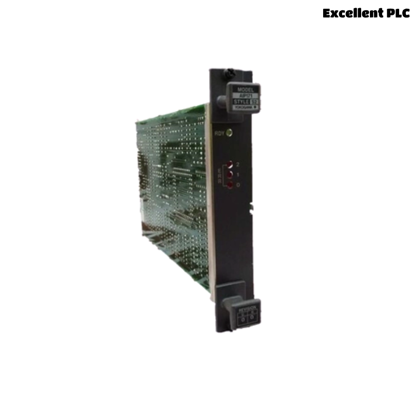
The Yokogawa AIP171 V net Transceiver Control Unit is a dedicated communication interface module used in Yokogawa CENTUM Distributed Control Systems (DCS). It manages high-speed data exchange between Field Control Stations (FCS), Human Interface Stations (HIS), Engineering Stations (ENG), gateways, and other control network devices connected through the V net communication network. Because the AIP171 serves as a key communication node, failures involving power supplies, network cabling, connectors, transceiver hardware, or configuration can interrupt real-time data exchange and affect plant operation. A systematic troubleshooting procedure enables maintenance engineers to quickly identify communication faults, restore network availability, and minimize production downtime.
Contents
- 1. Understanding Communication Faults
- 2. Common Failure Symptoms
- 3. Typical Causes of Network Faults
- 4. Initial Hardware Inspection
- 5. Power Supply Diagnostics
- 6. V net Communication Diagnostics
- 7. Connector and Cable Inspection
- 8. Diagnostic Log Analysis
- 9. Recommended Troubleshooting Workflow
- 10. Corrective Actions
- 11. Functional Recovery Verification
- 12. Preventive Maintenance
- 13. Real Industrial Maintenance Case
- 14. Frequently Asked Questions
Understanding Communication Faults
The AIP171 is responsible for reliable communication over the Yokogawa V net control network. Communication interruptions may isolate controllers, operator stations, or engineering workstations, resulting in delayed monitoring, alarm reporting, or control system diagnostics. Most communication problems originate from external wiring, network topology errors, connector issues, or power disturbances rather than internal hardware failure.
Common Failure Symptoms
- Loss of V net communication.
- Operator station cannot communicate with controllers.
- Engineering workstation connection failure.
- Intermittent communication alarms.
- Network timeout messages.
- Status LED indicates communication fault.
- Unexpected communication interruptions.
- Network synchronization errors.
Typical Causes of Network Faults
- Power supply instability.
- Damaged V net communication cable.
- Loose communication connectors.
- Incorrect network topology.
- Connector contamination or corrosion.
- Improper grounding.
- Faulty communication port.
- Hardware failure within the transceiver module.
Initial Hardware Inspection
- Verify module installation.
- Inspect communication status LEDs.
- Check communication connectors.
- Inspect communication cables.
- Verify cabinet ventilation.
Power Supply Diagnostics
- Measure supply voltage.
- Inspect power wiring.
- Verify protective devices.
- Check grounding continuity.
- Review power-related alarm history.
V net Communication Diagnostics
- Verify communication cable continuity.
- Inspect network topology.
- Review communication statistics.
- Verify communication with connected stations.
- Monitor network error counters.
Connector and Cable Inspection
- Inspect connector pins.
- Verify secure connector engagement.
- Replace damaged communication cables.
- Clean oxidized contacts.
- Inspect cable routing for mechanical damage.
Diagnostic Log Analysis
| Observed Condition | Possible Diagnosis |
|---|---|
| No network communication | Power failure or communication cable fault |
| Intermittent communication | Loose connector or damaged cable |
| Network timeout | Topology or communication interruption |
| Communication alarm | Transceiver interface or wiring problem |
| Status LED fault | Internal module or communication hardware failure |
Always verify communication cables, connectors, and network topology before replacing the AIP171 module.
Recommended Troubleshooting Workflow
VERIFY POWER SUPPLY
CHECK MODULE STATUS
INSPECT CONNECTORS
VERIFY COMMUNICATION CABLES
CHECK NETWORK TOPOLOGY
REVIEW DIAGNOSTIC LOGS
IDENTIFY ROOT CAUSE
IMPLEMENT CORRECTIVE ACTION
VERIFY NETWORK RECOVERY
MONITOR COMMUNICATION STABILITY
A systematic troubleshooting workflow reduces maintenance time and minimizes unnecessary replacement of communication hardware.
Corrective Actions
- Restore stable power supplies.
- Reconnect loose communication cables.
- Replace damaged connectors.
- Correct network topology.
- Clean contaminated communication contacts.
- Improve cabinet grounding.
- Replace defective communication cables.
- Replace the AIP171 module only after confirming internal hardware failure.
Functional Recovery Verification
- Verify module startup.
- Confirm stable V net communication.
- Validate communication with all connected stations.
- Review diagnostic logs.
- Monitor network stability during production.
Preventive Maintenance
- Inspect communication connectors regularly.
- Check cable routing and insulation.
- Review communication diagnostics periodically.
- Maintain cabinet cleanliness.
- Keep network documentation up to date.
Real Industrial Maintenance Case
At a power generation facility, operators reported repeated communication interruptions between the engineering workstation and several field control stations.
Inspection determined that one V net communication connector on the AIP171 had become partially disengaged due to cabinet vibration during long-term operation.
After reseating the connector and securing the cable:
- Communication recovered immediately.
- Network timeout alarms disappeared.
- Engineering workstation access was restored.
- The control network remained stable throughout subsequent operation.
Frequently Asked Questions
Why does the AIP171 lose communication?
The most common causes are damaged communication cables, loose connectors, unstable power supplies, incorrect network topology, or poor grounding.
How can intermittent communication faults be diagnosed?
Inspect communication connectors, monitor network error counters, verify cable continuity, review diagnostic logs, and check for mechanical vibration or connector contamination.
When should the AIP171 module be replaced?
The module should only be replaced after verifying power integrity, communication wiring, connector condition, network configuration, grounding, and diagnostic information confirms an internal hardware failure.
Summary
Effective troubleshooting of the Yokogawa AIP171 V net Transceiver Control Unit requires systematic inspection of power supplies, communication cables, connectors, network topology, grounding, and diagnostic information. Following a structured troubleshooting methodology helps restore stable V net communications, improve network reliability, reduce downtime, and prevent unnecessary replacement of communication modules.