

The Yokogawa AIP181 Communication Module is an industrial communication interface designed for Yokogawa Distributed Control Systems (DCS). It provides reliable data exchange between Field Control Stations (FCS), Human Interface Stations (HIS), Engineering Stations (ENG), gateways, remote I/O equipment, and supervisory control systems. Supporting high-speed industrial communications and continuous operation, the AIP181 enables deterministic data transmission for process control applications in industries such as oil and gas, petrochemical, chemical processing, power generation, water treatment, and manufacturing. Proper installation, wiring, grounding, and commissioning are essential to ensure dependable communication performance and long-term system reliability.
Contents
- 1. Product Overview
- 2. Main Features
- 3. Typical Applications
- 4. Installation Preparation
- 5. Hardware Inspection
- 6. Module Installation
- 7. Power Connections
- 8. Communication Wiring
- 9. Grounding Requirements
- 10. Commissioning Procedure
- 11. Functional Testing
- 12. Preventive Maintenance
- 13. Practical Installation Case
- 14. Frequently Asked Questions
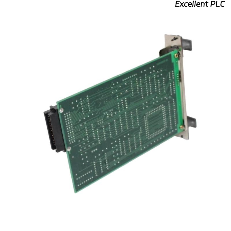
Product Overview
The AIP181 Communication Module provides reliable network communication between Yokogawa control equipment and distributed automation devices. It processes communication traffic, maintains stable data exchange, and supports continuous industrial operation under demanding environmental conditions.
Main Features
- Industrial communication interface module
- High-speed data transmission
- Reliable real-time communication
- Compact modular design
- Continuous industrial operation
- High communication stability
- Flexible system integration
- Industrial-grade reliability
Typical Applications
- Yokogawa Distributed Control Systems
- Industrial communication networks
- Oil and gas processing
- Petrochemical plants
- Power generation facilities
- Large-scale process automation systems
Installation Preparation
- Review system network documentation.
- Verify module compatibility.
- Prepare cabinet installation location.
- Inspect communication cables.
- Confirm power availability.
Hardware Inspection
- Verify module model number.
- Inspect communication connectors.
- Inspect module housing.
- Verify supplied accessories.
- Check for shipping damage.
Module Installation
- Disconnect cabinet power.
- Insert the module into the designated rack slot.
- Secure the retaining mechanism.
- Verify connector engagement.
- Inspect module alignment.
Power Connections
- Connect the specified power source.
- Verify supply voltage.
- Inspect protective devices.
- Verify wiring polarity.
- Confirm power indicators after startup.
Communication Wiring
- Connect communication cables.
- Verify network addressing.
- Inspect connector engagement.
- Label communication cables.
- Verify communication indicators.
Grounding Requirements
- Connect protective earth.
- Maintain low grounding resistance.
- Avoid ground loops.
- Verify cabinet grounding continuity.
- Inspect grounding periodically.
Commissioning Procedure
VERIFY INSTALLATION
CONNECT POWER
VERIFY GROUNDING
CONNECT COMMUNICATION NETWORK
POWER UP MODULE
VERIFY COMMUNICATION STATUS
TEST NETWORK CONNECTIONS
VALIDATE SYSTEM OPERATION
START NORMAL SERVICE
Functional Testing
- Verify module startup.
- Confirm communication status.
- Test communication with connected devices.
- Review diagnostic information.
- Monitor network stability.
Preventive Maintenance
- Inspect communication connectors regularly.
- Review communication diagnostics.
- Inspect cable insulation.
- Maintain cabinet ventilation.
- Keep communication documentation updated.
Practical Installation Case
During commissioning of a chemical plant automation system, engineers observed that an AIP181 module could not establish communication with several remote devices.
Inspection found that one communication cable had been terminated incorrectly during installation.
After correcting the wiring:
- Communication was immediately restored.
- All connected devices became accessible.
- Network diagnostics indicated normal operation.
- The control system entered stable production service.
Frequently Asked Questions
What is the primary function of the AIP181?
The AIP181 Communication Module manages industrial network communications between Yokogawa control equipment and connected automation devices.
Can the module operate continuously?
Yes. The AIP181 is designed for continuous industrial operation and supports high-availability communication required for process automation.
What should be checked before startup?
Verify module installation, power wiring, communication connections, grounding, network configuration, and communication indicators before commissioning.
Summary
Proper installation of the Yokogawa AIP181 Communication Module requires careful hardware inspection, secure rack installation, correct communication wiring, reliable power connections, effective grounding, and comprehensive commissioning. Following these procedures ensures dependable industrial communications, stable system integration, and long-term automation reliability.