 Excellent PLC


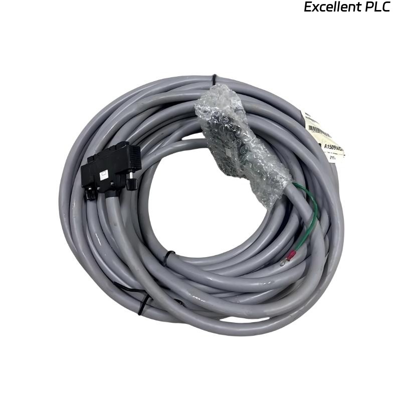
The Yokogawa AKB335 Signal Cable is an industrial-grade interconnection cable designed for use in Yokogawa CENTUM VP and CENTUM CS Distributed Control Systems (DCS). It provides dependable signal transmission between Field Control Units (FCUs), I/O modules, communication interface units, terminal boards, and other control system components. Manufactured with high-quality conductors, durable insulation, and effective electromagnetic shielding, the AKB335 minimizes electrical noise while maintaining reliable analog and digital signal integrity. Proper installation, cable routing, and grounding practices are essential to ensure long-term communication reliability and stable system performance.
Contents
- 1. Product Overview
- 2. Main Features
- 3. Typical Applications
- 4. Installation Preparation
- 5. Cable Inspection
- 6. Cable Installation
- 7. Cable Routing Guidelines
- 8. Electrical Connection
- 9. Commissioning Procedure
- 10. Functional Verification
- 11. Preventive Maintenance
- 12. Practical Installation Case
- 13. Frequently Asked Questions
Product Overview
The AKB335 Signal Cable is engineered to provide secure and noise-resistant electrical connections between Yokogawa automation system components. Its shielded construction protects process signals from electromagnetic interference (EMI), ensuring accurate communication and dependable control system operation in demanding industrial environments.
Main Features
- Industrial-grade signal transmission cable
- Compatible with Yokogawa CENTUM VP and CENTUM CS systems
- Shielded construction for EMI protection
- High-quality insulated conductors
- Flexible cable for control cabinet installation
- Reliable analog and digital signal transmission
- Designed for continuous industrial operation
Typical Applications
- CENTUM VP Distributed Control Systems
- CENTUM CS automation systems
- Field Control Unit (FCU) wiring
- I/O module interconnections
- Communication interface units
- Terminal board connections
- Industrial control cabinets
- Oil and gas production facilities
- Petrochemical plants
- Power generation stations
Installation Preparation
- Verify the AKB335 part number and cable length.
- Review engineering wiring diagrams.
- Inspect the planned cable routing path.
- Prepare cable clamps and mounting hardware.
- Observe ESD protection procedures throughout installation.
Cable Inspection
- Inspect the cable jacket for cuts, cracks, or abrasion.
- Verify connector integrity.
- Check conductor insulation.
- Inspect shielding condition.
- Confirm cable identification labels.
Cable Installation
- Power down associated equipment before installation.
- Route the cable according to approved engineering drawings.
- Avoid excessive bending and twisting.
- Connect both cable ends securely.
- Fasten the cable using approved supports.
- Verify connector locking mechanisms.
Cable Routing Guidelines
- Maintain separation between signal and power cables.
- Observe the recommended minimum bend radius.
- Avoid routing near motors, transformers, or variable-frequency drives.
- Support long cable runs adequately.
- Protect the cable against mechanical damage.
Electrical Connection
- Verify connector orientation.
- Ensure connectors are fully engaged.
- Confirm shield grounding according to engineering requirements.
- Inspect connector locking devices.
- Verify wiring matches system documentation.
Commissioning Procedure
VERIFY CABLE IDENTIFICATION
INSPECT CONNECTORS
ROUTE THE CABLE
CONNECT BOTH ENDS
VERIFY SHIELD GROUNDING
CHECK SIGNAL CONTINUITY
POWER THE SYSTEM
VERIFY NORMAL COMMUNICATION
Functional Verification
- Verify stable signal transmission.
- Confirm communication between connected devices.
- Check for communication alarms.
- Inspect connector stability.
- Monitor overall control system performance.
Preventive Maintenance
- Inspect cables during routine maintenance.
- Verify connector tightness.
- Inspect cable insulation for deterioration.
- Check shielding integrity.
- Replace damaged cables promptly.
Practical Installation Case
During modernization of a power plant control system, AKB335 signal cables were installed between remote I/O cabinets and communication interface modules.
After installation and commissioning:
- Signal transmission remained stable.
- No EMI-related communication errors occurred.
- Control system diagnostics showed normal operation.
- The automation system operated continuously without communication interruptions.
Frequently Asked Questions
What is the AKB335 Signal Cable used for?
The AKB335 is used for reliable analog and digital signal transmission between Yokogawa DCS controllers, I/O modules, communication interface units, and terminal boards.
Why should shield grounding be verified?
Proper shield grounding minimizes electromagnetic interference and helps maintain signal integrity throughout the control system.
What should be verified after installation?
Verify connector engagement, cable routing, shield grounding, electrical continuity, communication quality, and proper operation of all connected equipment.
Summary
Proper installation of the Yokogawa AKB335 Signal Cable ensures reliable communication throughout CENTUM VP and CENTUM CS Distributed Control Systems. Correct routing, secure connector installation, effective shield grounding, and routine preventive maintenance maximize signal integrity and support dependable long-term industrial automation performance.