 Excellent PLC


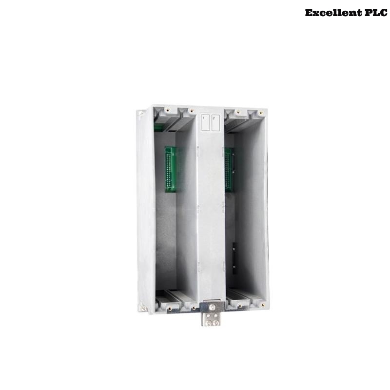
The Yokogawa AMN51 Communication Card Nest is a dedicated rack assembly for communication cards used in Yokogawa CENTUM CS 1000, CENTUM CS 3000, CENTUM VP, and Compact Field Control Station (Compact FCS) Distributed Control Systems (DCS). The AMN51 provides mechanical support, BN-bus backplane communication, power distribution, and communication interfaces for Ethernet and serial communication cards. The rack itself does not execute communication protocols; all protocol processing is performed by the installed communication cards. Because several communication cards share the same rack infrastructure, AMN51-related faults may interrupt communications between the DCS and multiple external systems simultaneously.
Contents
- 1. Understanding Communication Rack Faults
- 2. Common Failure Symptoms
- 3. Typical Causes
- 4. Initial Hardware Inspection
- 5. Communication Card Verification
- 6. Network and Cable Inspection
- 7. Diagnostic Analysis
- 8. Recommended Troubleshooting Workflow
- 9. Corrective Actions
- 10. Functional Recovery Verification
- 11. Preventive Maintenance
- 12. Industrial Maintenance Case
- 13. Frequently Asked Questions
Understanding Communication Rack Faults
The AMN51 provides the communication platform between the Yokogawa controller and external industrial devices. Communication problems may result from poor card installation, damaged BN-bus connectors, faulty Ethernet or serial cables, incorrect communication parameters, network hardware failures, or inadequate grounding. Because multiple communication cards share the same rack and power distribution, a single rack-level fault may affect several communication channels at once.
Common Failure Symptoms
- Communication cards are not detected by the controller.
- Ethernet communication is interrupted.
- Serial communication repeatedly times out.
- PLC or SCADA data stops updating.
- Frequent communication alarms appear in the DCS.
- Communication status LEDs indicate hardware faults.
- Several communication ports fail simultaneously.
- Engineering workstation cannot communicate with the controller.
Typical Causes
- Loose communication card installation.
- Damaged BN-bus backplane connector.
- Faulty Ethernet or serial communication cable.
- Incorrect IP address or communication parameters.
- Poor cable shielding or grounding.
- Network switch or external device malfunction.
- Rack power distribution problem.
- Internal AMN51 hardware failure.
Initial Hardware Inspection
- Verify rack mounting security.
- Inspect communication card seating.
- Check BN-bus connectors.
- Inspect Ethernet and serial connectors.
- Verify rack power status.
- Inspect cabinet cooling and cleanliness.
Communication Card Verification
- Reseat communication cards.
- Verify slot assignments.
- Inspect diagnostic LEDs.
- Review DCS diagnostic logs.
- Confirm controller recognition of all communication cards.
- Test suspected cards in another compatible rack if available.
Network and Cable Inspection
- Verify Ethernet link indicators.
- Inspect cable continuity.
- Confirm IP configuration.
- Check communication protocol settings.
- Inspect cable shielding.
- Verify grounding continuity.
Diagnostic Analysis
| Observed Condition | Possible Diagnosis |
|---|---|
| All communication cards offline | Rack power or BN-bus communication failure |
| Single communication card unavailable | Card hardware fault or improper installation |
| Ethernet link inactive | Cable, switch, or connector problem |
| Communication timeout alarms | Incorrect configuration or external device failure |
| Multiple communication channels unavailable | Backplane connector or rack hardware fault |
Recommended Troubleshooting Workflow
CHECK DCS DIAGNOSTICS
VERIFY RACK POWER
CHECK CARD INSTALLATION
VERIFY BN-BUS CONNECTION
CHECK NETWORK CABLING
VERIFY COMMUNICATION PARAMETERS
TEST EXTERNAL DEVICE COMMUNICATION
CONFIRM SYSTEM RECOVERY
Corrective Actions
- Reseat communication cards.
- Replace damaged communication cables.
- Repair or replace faulty connectors.
- Correct communication configuration.
- Restore proper grounding and shielding.
- Repair rack power connections.
- Replace defective communication cards.
- Replace the AMN51 rack if hardware failure is confirmed.
Functional Recovery Verification
- Confirm all communication cards are recognized.
- Verify stable Ethernet communication.
- Confirm successful serial communication.
- Monitor communication error counters.
- Verify controller diagnostics indicate normal operation.
- Perform extended communication testing.
Preventive Maintenance
- Inspect communication card seating regularly.
- Clean communication connectors.
- Verify Ethernet cable integrity.
- Inspect grounding connections.
- Review communication diagnostics.
- Maintain proper cabinet ventilation.
Industrial Maintenance Case
During routine operation at a combined-cycle power plant, communication between the Yokogawa CENTUM VP system and several PLCs became unstable. Multiple communication alarms appeared simultaneously, and the engineering workstation intermittently lost connectivity.
Inspection revealed oxidation on the BN-bus connector within the AMN51 communication card rack. After shutting down the affected rack, maintenance personnel cleaned the connectors, reseated all communication cards, verified Ethernet cable integrity, and restored proper grounding.
- All communication cards were detected normally.
- Ethernet communication stabilized.
- PLC data updated without interruption.
- All communication alarms were cleared during long-term monitoring.
Frequently Asked Questions
Does the AMN51 process Ethernet or serial communication protocols?
No. Protocol processing is handled entirely by the installed communication cards. The AMN51 provides only the rack infrastructure, BN-bus interface, and power distribution.
Why can one AMN51 fault affect several communication links?
Because multiple communication cards share the same BN-bus backplane, power supply, and rack connections, a rack-level hardware problem can interrupt communications across multiple network interfaces simultaneously.
What should be checked before replacing the AMN51?
Verify rack power, BN-bus connections, communication card seating, Ethernet and serial cables, communication parameters, network equipment, grounding, and controller diagnostics before determining that the AMN51 rack itself has failed.
Summary
Effective troubleshooting of the Yokogawa AMN51 Communication Card Nest requires systematic inspection of rack power, BN-bus connections, communication card installation, network cabling, protocol configuration, grounding, and DCS diagnostics. Routine preventive maintenance minimizes communication failures, improves network reliability, and ensures stable long-term operation of Yokogawa CENTUM Distributed Control Systems.