 Excellent PLC


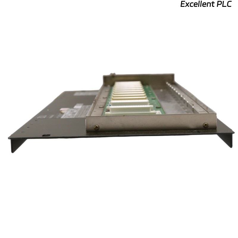
The Yokogawa ANR10D Dual-Redundant ER Bus Node Unit is a remote Field I/O (FIO) node used in Yokogawa CENTUM VP and CENTUM CS 3000 Distributed Control Systems (DCS). It communicates with the Field Control Unit (FCU) through an EB401 ER Bus Interface Master Module over a dual-redundant Enhanced Remote (ER) Bus. The ANR10D provides power distribution, backplane communication, and installation space for analog and digital FIO modules. Since one ANR10D typically serves numerous field devices, failures involving the node unit, ER Bus communication, or power distribution can interrupt multiple process measurements and control signals simultaneously.
Contents
- 1. Understanding ER Bus Node Faults
- 2. Common Failure Symptoms
- 3. Typical Causes
- 4. Initial Hardware Inspection
- 5. Power Supply Verification
- 6. ER Bus Communication Inspection
- 7. I/O Module Verification
- 8. Diagnostic Analysis
- 9. Recommended Troubleshooting Workflow
- 10. Corrective Actions
- 11. Functional Recovery Verification
- 12. Preventive Maintenance
- 13. Industrial Maintenance Case
- 14. Frequently Asked Questions
Understanding ER Bus Node Faults
The ANR10D functions as a communication gateway between the ER Bus network and the installed FIO modules. Problems involving ER Bus cables, interface modules, redundant communication channels, power supply modules, or backplane connections may cause remote node communication failures, loss of field signals, or redundancy alarms. Effective troubleshooting should determine whether the fault originates from the ER Bus network, the ANR10D hardware, installed I/O modules, the EB401 master interface, or controller configuration.
Common Failure Symptoms
- The remote node is not detected by the Field Control Unit.
- ER Bus communication alarms appear in the DCS.
- Remote analog and digital I/O become unavailable.
- One ER Bus communication channel reports a fault.
- Repeated communication switchover occurs.
- I/O modules are not recognized.
- Node status LEDs indicate communication or hardware errors.
- Process values from the remote cabinet disappear.
Typical Causes
- Loose ER Bus communication cable.
- Damaged ER Bus connector.
- Power supply module failure.
- Improper installation of the ER Bus interface module.
- Incorrect node address configuration.
- Backplane connector contamination.
- Poor grounding or shielding.
- EB401 master interface communication failure.
- Internal ANR10D hardware failure.
Initial Hardware Inspection
- Verify cabinet installation security.
- Inspect ER Bus cable connectors.
- Check redundant power supply indicators.
- Verify module locking mechanisms.
- Inspect cabinet cooling and ventilation.
- Confirm grounding continuity.
Power Supply Verification
- Verify primary power supply operation.
- Confirm redundant power supply availability.
- Measure supply voltage.
- Inspect power connectors.
- Check power module diagnostic LEDs.
- Verify automatic power redundancy operation.
ER Bus Communication Inspection
- Inspect ER Bus A communication.
- Inspect ER Bus B communication.
- Verify cable continuity.
- Check connector locking mechanisms.
- Inspect cable routing.
- Verify communication redundancy.
I/O Module Verification
- Reseat installed FIO modules.
- Inspect ER Bus interface module.
- Verify module slot assignments.
- Review DCS diagnostic logs.
- Confirm node address configuration.
- Test suspected modules in another compatible node if available.
Diagnostic Analysis
| Observed Condition | Possible Diagnosis |
|---|---|
| Entire remote node offline | Power supply failure or complete ER Bus communication loss |
| Only ER Bus A fails | Primary communication cable or connector fault |
| Only ER Bus B fails | Redundant communication cable fault |
| Repeated communication switchover | Intermittent cable or connector problem |
| Installed I/O modules unavailable | Backplane or node hardware failure |
Recommended Troubleshooting Workflow
CHECK DCS DIAGNOSTICS
VERIFY POWER SUPPLIES
CHECK ER BUS A
CHECK ER BUS B
VERIFY NODE ADDRESS
INSPECT I/O MODULES
TEST REDUNDANCY
CONFIRM SYSTEM RECOVERY
Corrective Actions
- Reconnect loose ER Bus cables.
- Replace damaged communication cables.
- Clean connector contacts.
- Replace faulty power supply modules.
- Correct node configuration.
- Restore grounding integrity.
- Replace defective interface modules.
- Replace the ANR10D node unit if internal hardware failure is confirmed.
Functional Recovery Verification
- Confirm the FCU recognizes the remote node.
- Verify both ER Bus communication channels operate normally.
- Confirm all installed I/O modules communicate correctly.
- Test automatic communication redundancy.
- Verify communication alarms are cleared.
- Monitor long-term communication stability.
Preventive Maintenance
- Inspect ER Bus connectors regularly.
- Verify redundant power supplies.
- Check module seating.
- Review communication diagnostics.
- Inspect grounding continuity.
- Perform scheduled redundancy testing.
Industrial Maintenance Case
At a large petrochemical complex, operators reported intermittent communication alarms affecting a remote instrument building connected through an ANR10D ER Bus Node Unit. The DCS indicated repeated communication path switching while several field measurements occasionally became unavailable.
Maintenance personnel inspected the node and found that one ER Bus connector had loosened due to prolonged cabinet vibration. After reconnecting the cable, cleaning the contacts, verifying communication redundancy, and confirming proper node configuration:
- Both ER Bus communication channels operated normally.
- All remote I/O modules were recognized.
- Communication alarms disappeared.
- The distributed control system remained stable during extended operational testing.
Frequently Asked Questions
Does the ANR10D process field signals?
No. Analog and digital signal processing is performed entirely by the installed FIO I/O modules. The ANR10D provides power distribution, backplane connectivity, and ER Bus communication.
Why does the system continue operating if one ER Bus channel fails?
The ANR10D supports dual-redundant ER Bus communication. When one communication channel becomes unavailable, the controller automatically switches to the remaining healthy channel, maintaining communication with the remote node.
What should be checked before replacing the ANR10D?
Verify redundant power supplies, ER Bus A and Bus B communication cables, node addressing, interface modules, installed I/O modules, grounding, EB401 master interface status, and controller diagnostics before determining that the ANR10D hardware has failed.
Summary
Effective troubleshooting of the Yokogawa ANR10D Dual-Redundant ER Bus Node Unit requires systematic inspection of redundant power supplies, ER Bus communication channels, interface modules, installed I/O modules, grounding, and DCS diagnostics. Routine preventive maintenance and periodic redundancy testing help ensure reliable remote Field I/O communication and continuous operation of Yokogawa CENTUM Distributed Control Systems.