 Excellent PLC


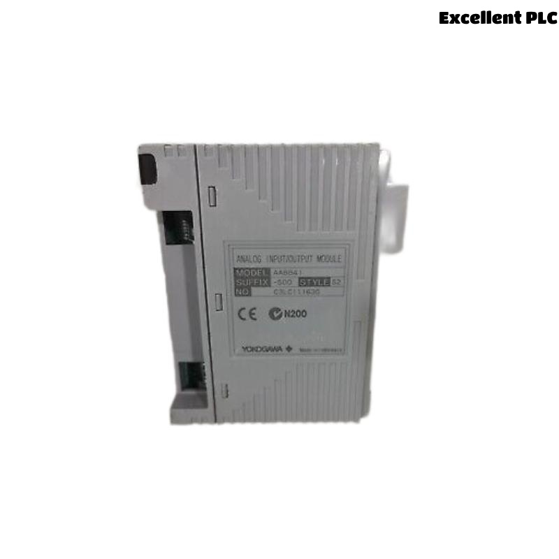
The Yokogawa ASD533 Digital Output Module is an 8-channel isolated digital output module designed for Yokogawa CENTUM VP and CENTUM CS 3000 Distributed Control Systems (DCS). The module provides isolated status outputs for driving intrinsically safe field devices such as solenoid valves, relays, pilot lamps, annunciators, and interface relays. The ASD533 incorporates built-in intrinsic safety barriers, making it suitable for hazardous area applications while providing excellent electrical isolation and reliable output performance.
Contents
- 1. Product Overview
- 2. Main Features
- 3. Typical Applications
- 4. Installation Preparation
- 5. Module Installation
- 6. Field Wiring
- 7. System Configuration
- 8. Commissioning Procedure
- 9. Functional Verification
- 10. Preventive Maintenance
- 11. Practical Installation Case
- 12. Frequently Asked Questions
Product Overview
The ASD533 provides eight isolated digital output channels for transmitting ON/OFF control signals from the DCS to field equipment. Each output channel is electrically isolated and incorporates an intrinsic safety interface suitable for hazardous process environments. The module connects through ATSD3S or ATSD3D pressure-clamp terminal blocks.
Main Features
- 8 isolated digital output channels
- Built-in intrinsic safety barrier
- Output voltage up to 26 VDC (open circuit)
- 10 ms output response time
- 1500 VAC isolation withstand voltage
- Status output function
- Pressure clamp terminal connection
- Continuous industrial operation
Typical Applications
- Solenoid valve control
- Relay output control
- Alarm annunciators
- Indicator lamps
- Motor starter interlocks
- Shutdown system outputs
- Hazardous area control circuits
- Petrochemical and refinery automation
Installation Preparation
- Verify the ASD533 model and suffix code.
- Confirm compatible FIO node installation.
- Prepare ATSD3S or ATSD3D terminal blocks.
- Inspect output wiring.
- Verify cabinet grounding.
- Review loop wiring drawings.
- Confirm field load specifications.
Module Installation
- Turn off cabinet power.
- Insert the ASD533 into the designated I/O slot.
- Secure the module firmly.
- Install the digital output terminal block.
- Connect field output wiring.
- Verify output polarity and channel assignment.
- Inspect all wiring before energizing the system.
Field Wiring
- Use approved industrial field cables.
- Wire each output according to loop drawings.
- Verify terminal numbering.
- Separate output wiring from AC power cables.
- Ground the cabinet correctly.
- Label all output circuits.
System Configuration
- Create the digital output module in CENTUM engineering software.
- Assign output tag names.
- Configure output logic.
- Download controller configuration.
- Verify communication with the FIO node.
- Review module diagnostics.
Commissioning Procedure
VERIFY MODULE INSTALLATION
CHECK POWER STATUS
VERIFY FIELD WIRING
POWER UP SYSTEM
CHECK MODULE DIAGNOSTICS
TEST ALL OUTPUT CHANNELS
VERIFY FIELD DEVICE OPERATION
CONFIRM NORMAL OPERATION
Functional Verification
- Verify all eight output channels operate correctly.
- Operate each connected field device.
- Confirm relay and solenoid response.
- Verify DCS command execution.
- Review diagnostic messages.
- Confirm stable output operation.
Preventive Maintenance
- Inspect terminal tightness regularly.
- Check field cable insulation.
- Verify cabinet grounding.
- Review diagnostic history.
- Inspect connected field devices.
- Perform scheduled output function tests.
Practical Installation Case
A refinery modernization project required reliable control of intrinsically safe solenoid valves in a hazardous process unit. Engineers installed ASD533 Digital Output Modules to control the valve circuits. After completing module installation, field wiring, controller configuration, and output verification, all eight output channels operated correctly, providing stable and reliable control of the field equipment while meeting intrinsic safety requirements.
Frequently Asked Questions
How many output channels does the ASD533 provide?
The ASD533 provides eight isolated digital output channels with built-in intrinsic safety barriers.
Which terminal blocks are used with the ASD533?
The ASD533 uses ATSD3S or ATSD3D pressure-clamp terminal blocks depending on the installation configuration.
What types of field devices can the ASD533 control?
The module is suitable for driving intrinsically safe field devices such as relays, solenoid valves, indicator lamps, annunciators, and interface relays within its specified electrical ratings.
Summary
The Yokogawa ASD533 Digital Output Module provides reliable 8-channel isolated digital output control for hazardous-area field devices in Yokogawa CENTUM Distributed Control Systems. Proper installation, correct wiring, accurate configuration, and comprehensive commissioning ensure dependable output control, high electrical isolation, and long-term operational reliability.