

Detailed Navigation
- Controller Overview
- System Architecture Role
- Environment Requirements
- Pre-Installation Audit
- Mechanical Installation
- Power Interface Setup
- Signal Wiring Strategy
- Configuration Loading
- Commissioning Method
- Runtime Verification
- Handover Checklist
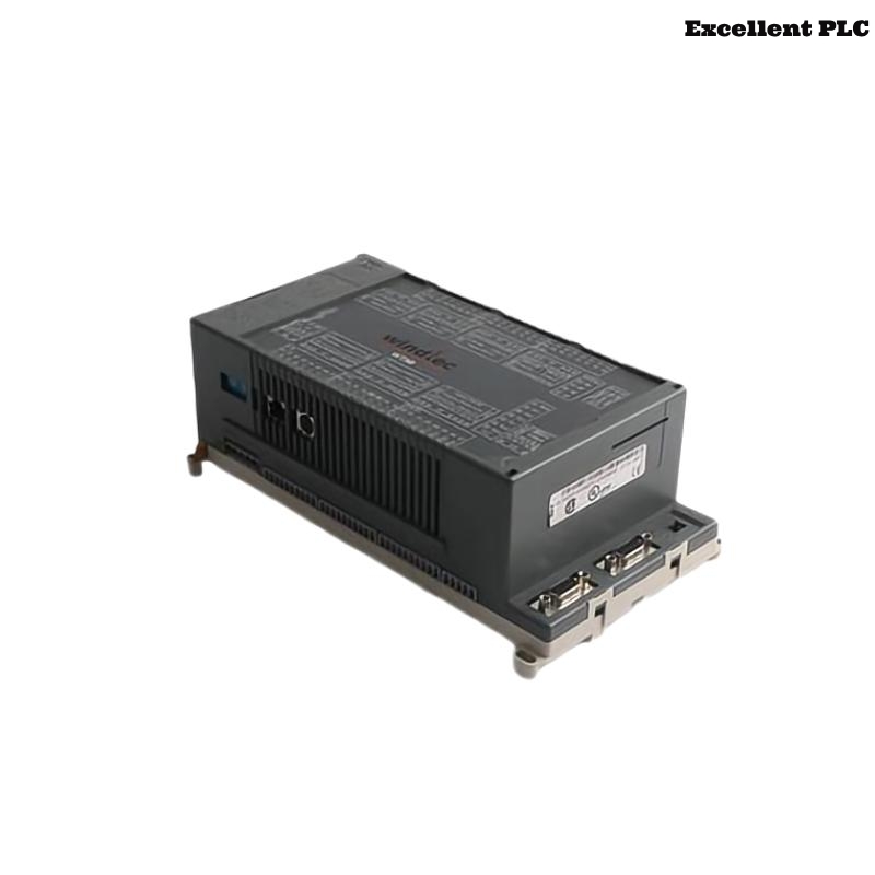
Controller Overview
The ABB 07KT98 H1 GIR5253100R0270 PLC Controller is a central automation unit used in Procontic systems for executing logic control, managing distributed I/O communication, and maintaining deterministic system behavior.
This Installation Guide focuses on Setup and Commissioning practices derived from real industrial deployments, ensuring reliable system startup and long-term operation.
System Architecture Role
Within a typical automation system, this PLC Controller performs:
- Central processing of control algorithms
- Coordination of multiple I/O racks
- Communication with supervisory systems
- Maintenance of System Configuration consistency
Improper integration at this level can affect the entire control network.
Environment Requirements
- Stable DC supply with minimal voltage fluctuation
- Proper cabinet ventilation and heat dissipation
- Low electromagnetic interference environment
- Secure grounding system with low resistance
Environmental instability often leads to future Troubleshooting challenges.
Pre-Installation Audit
Before installation, conduct a structured audit:
- Verify hardware compatibility with existing modules
- Confirm rack slot allocation against System Configuration
- Inspect connectors for wear or contamination
- Check availability of updated firmware and project files
- Validate wiring layout planning
This audit reduces installation risks significantly.
Mechanical Installation
- Align PLC Controller with rack guide rails carefully
- Insert partially and verify backplane alignment
- Apply steady pressure until fully seated
- Secure locking clips firmly
Incorrect seating may lead to intermittent communication issues that are difficult to diagnose.
Power Interface Setup
- Connect DC supply with correct polarity
- Ensure tight terminal connections
- Measure voltage stability under load
- Use dedicated power circuits where possible
Signal Wiring Strategy
- Separate signal cables from high-power lines
- Use shielded twisted-pair cables for communication
- Ground shielding at one side only
- Maintain consistent cable routing paths
Good wiring practices reduce future Fault Diagnosis complexity.
Configuration Loading
After hardware installation:
- Connect engineering workstation
- Load verified System Configuration
- Check module addressing and mapping
- Confirm communication parameters
Commissioning Method
Field engineers often apply a progressive commissioning method:
- Start PLC Controller independently
- Verify CPU status indicators
- Enable communication interfaces gradually
- Add I/O modules step by step
- Monitor diagnostics continuously
INITIAL_POWER_ON
VERIFY_CPU_STATE
LOAD_PROJECT
ENABLE_NETWORK
ADD_IO_MODULES
CHECK_SYSTEM_STATUS
Runtime Verification
- Simulate process signals under real load
- Monitor communication stability over time
- Check diagnostic logs for hidden faults
- Observe system behavior during peak operation
Handover Checklist
- All modules respond correctly
- No active faults in diagnostic buffer
- System restarts reliably
- Documentation and backups are complete
Completion of these checks ensures the PLC Controller is ready for production use.