

Contents
- Overview & Key Features
- Role of ABB 216AB61 in Automation
- Pre-Installation Checks
- Module Mounting Procedure
- Wiring Guidelines & EMI Precautions
- Startup & Commissioning Steps
- Field Testing & Verification
- Practical Engineer Tips
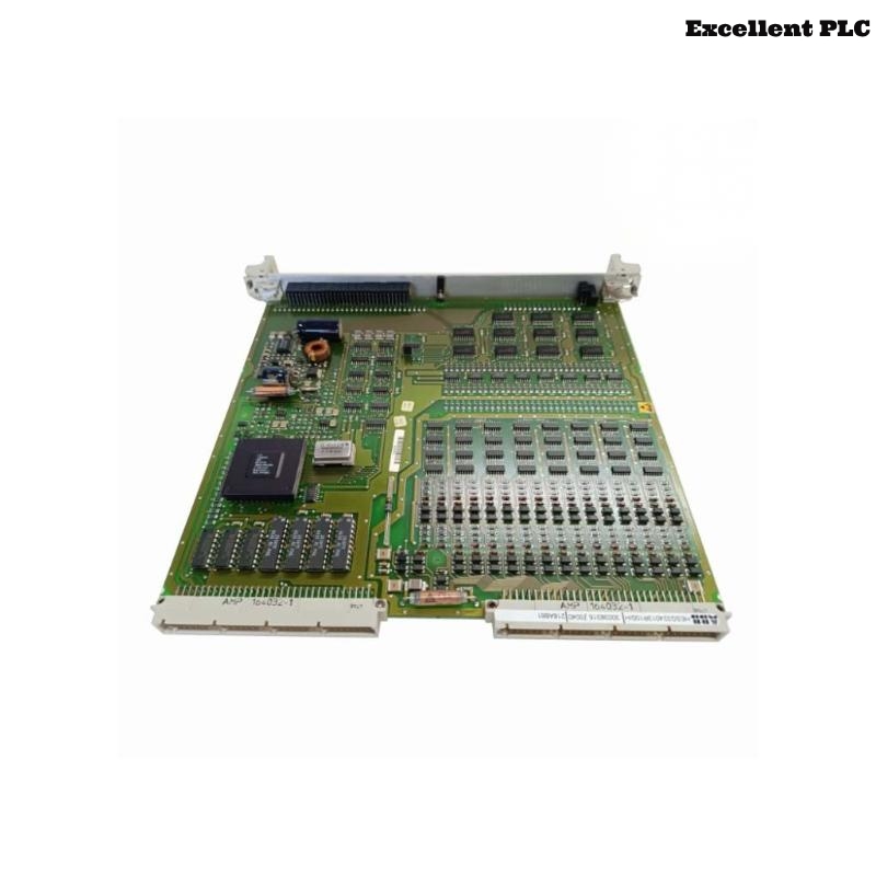
ABB 216AB61 PLC Module Overview & Key Features
The ABB 216AB61 PLC Module is widely used in industrial automation systems for precise control of digital and analog I/O modules. Proper installation and commissioning are critical to maintain system stability and reduce communication faults.
This guide also applies to variant HESG216881/A used in distributed Procontic systems.
Role of ABB 216AB61 in Automation Systems
- Controls digital and analog I/O modules in real-time
- Coordinates communication between multiple PLC controllers
- Maintains deterministic response for critical processes
- Provides built-in diagnostics for fault detection
Pre-Installation Checks for ABB 216AB61
- Check cabinet grounding (target < 1Ω)
- Verify DC supply voltage stability (±0.1V)
- Inspect cabinet layout for potential EMI sources
- Ensure System Configuration files match module placement
Module Mounting Procedure
- Align the 216AB61 module with the backplane rails
- Insert partially and check connector alignment
- Apply steady pressure to seat module fully
- Lock mechanical clips and confirm stability under vibration
Field cases indicate improper seating causes intermittent bus errors, often difficult to diagnose during high-speed operations.
Wiring Guidelines & EMI Precautions
- Keep communication lines separate from power cables
- Use shielded twisted-pair wiring for I/O buses
- Ground shielding at a single cabinet reference point
- Minimize cable length and avoid loops near inverters or motors
Startup & Commissioning Steps
- Power only the ABB 216AB61 module initially
- Verify CPU RUN/IDLE LEDs
- Load and verify System Configuration
- Enable communication bus without connected I/O
- Add I/O modules incrementally while monitoring diagnostics
POWER_ON_MODULE
VERIFY_LED_STATUS
LOAD_SYSTEM_CONFIG
ENABLE_COMM_BUS
ADD_IO_STEPWISE
MONITOR_DIAGNOSTICS
Field Testing & Verification
- Run system under full operational load for 2–3 hours
- Monitor CPU diagnostics and communication errors
- Simulate input disturbances to test analog/digital stability
- Confirm consistent system performance before production
Practical Engineer Tips
Common field issues include grounding errors, poor cable routing, and skipping staged commissioning. Following this guide ensures reliable operation and reduces future troubleshooting for ABB 216AB61 and HESG216881/A modules.