

Contents
- Overview & Key Features
- Role of ABB 216EA62 in Automation
- Pre-Installation Checks
- Mounting & Rack Integration Procedure
- Wiring Guidelines & EMI Considerations
- Startup & Commissioning Steps
- Field Testing & System Validation
- Practical Engineer Notes
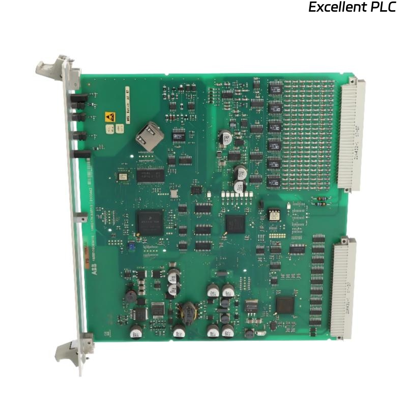
ABB 216EA62 PLC Module Overview & Key Features
The ABB 216EA62 PLC Module is a high-reliability module for controlling digital and analog I/O within Procontic automation systems. Proper Installation and Commissioning prevent communication faults and ensure consistent system performance.
This guide also applies to variant 1MRB150083R1/F used in distributed industrial control networks.
Role of ABB 216EA62 in Automation Systems
- Executes sequential and interlocking process control logic
- Coordinates multiple I/O modules for synchronized operation
- Ensures deterministic timing for critical processes
- Provides built-in diagnostics to detect faults early
Pre-Installation Checks for ABB 216EA62
- Verify cabinet grounding (≤1Ω)
- Check 24V DC supply stability (±0.1V)
- Inspect cabinet layout for potential EMI sources
- Confirm module placement matches System Configuration
Skipping these prechecks has led to intermittent communication failures in field projects.
Mounting & Rack Integration Procedure
- Align module with backplane rails and insert partially
- Visually check connector alignment
- Fully seat module with even pressure
- Lock mechanical clips and confirm stability under vibration
Field experience shows that improper seating causes sporadic bus errors, often only appearing during high-speed operations.
Wiring Guidelines & EMI Considerations
- Keep communication lines away from high-power cables
- Use shielded twisted-pair cables for I/O buses
- Ground shielding at a single cabinet reference point
- Minimize cable lengths and avoid loops near inverters
Startup & Commissioning Steps
- Power only the 216EA62 module initially
- Verify CPU RUN/IDLE LED status
- Load and validate System Configuration
- Enable communication bus without connected I/O modules
- Add I/O modules incrementally while monitoring diagnostics
POWER_ON_MODULE
VERIFY_LED_STATUS
LOAD_SYSTEM_CONFIG
ENABLE_BUS
ADD_IO_STEPWISE
MONITOR_DIAGNOSTICS
Field Testing & System Validation
- Run system under full operational load for 2–3 hours
- Monitor CPU diagnostics and communication error counters
- Simulate analog/digital input disturbances to verify response
- Confirm system stability before production start
Practical Engineer Notes
Most installation errors are due to grounding mistakes, poor cable routing, or skipped staged commissioning. Following this guide ensures stable operation and reduces future troubleshooting for ABB 216EA62 and 1MRB150083R1/F modules.