

Guide Structure
- Installation Overview
- System Context
- Critical Installation Risks
- Mounting Logic
- Wiring Strategy
- Commissioning Path
- Validation Check
- Engineer Note
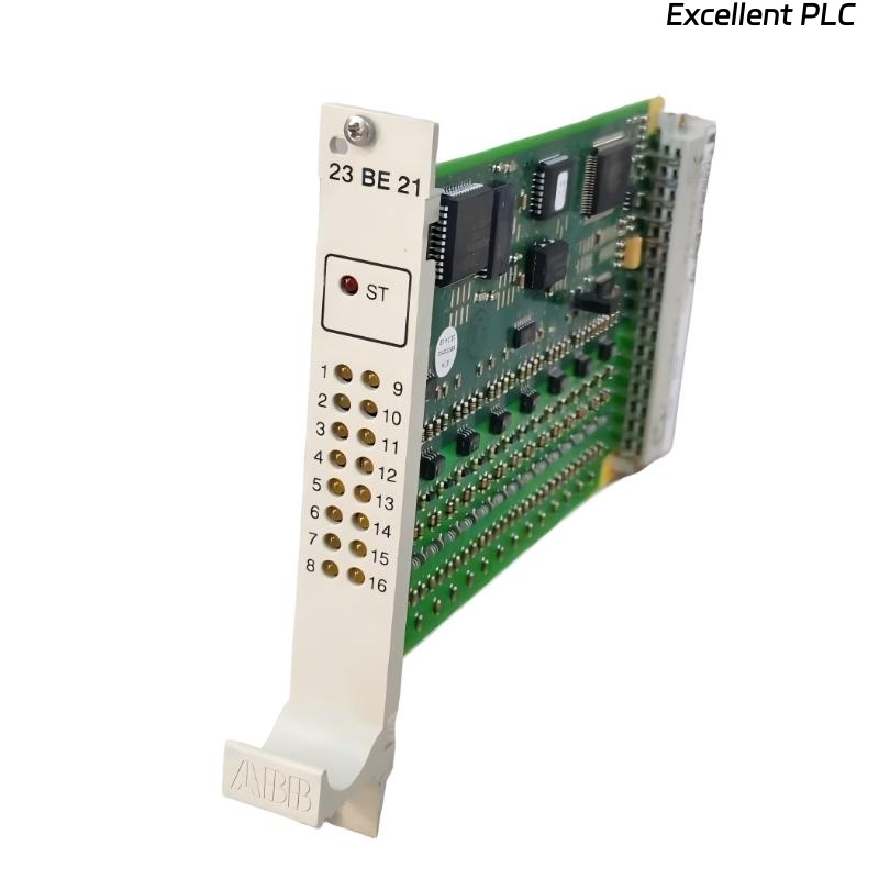
ABB 23BE21 PLC Module Installation Guide
ABB 23BE21 PLC module installation failures are often caused by incorrect wiring and incomplete system configuration rather than hardware defects. This Installation Guide explains how to perform proper Setup and Commissioning in real industrial scenarios.
The ABB 23BE21 Module (1KGT004900R5012) is typically used as an interface or processing module within ABB PLC controller systems.
ABB 23BE21 Role in PLC System Configuration
- Interfaces between PLC Controller and field devices
- Processes input/output signals
- Maintains stable communication within the control system
- Supports real-time control logic execution
Critical Risks During ABB 23BE21 Setup
Most Setup issues occur at three points:
- Incorrect module addressing
- Signal wiring mismatch
- Poor grounding causing unstable signals
In one commissioning case, a wrong address configuration caused all signals to shift, leading to system misoperation.
ABB 23BE21 Mounting Logic
- Insert module carefully into rack slot
- Ensure backplane connection is firm
- Avoid installation near high-heat modules
- Keep module accessible for maintenance
Signal Wiring Strategy for ABB 23BE21
- Separate signal and power cables
- Use shielded cables for analog signals
- Confirm terminal mapping before wiring
- Double-check polarity and signal direction
VERIFY_MODULE_ADDRESS
MAP_IO_CHANNELS
CHECK_SIGNAL_PATH
CONNECT_TERMINALS
VALIDATE_CONFIGURATION
ABB 23BE21 Commissioning Path
- Start system with minimal I/O connections
- Verify module detection in PLC Controller
- Enable signals step-by-step
- Observe system response after each step
Validation Check After Installation
- Confirm correct input readings
- Test output signal response
- Monitor communication stability
- Run system under simulated load
Engineer Note
From field experience, improper Setup during Installation is the main reason for later troubleshooting. Following a structured Installation Guide significantly reduces commissioning time and system instability.