

Table of Contents
- Bently Nevada 109548-01 Installation Overview
- Working Principle of 109548-01 Proximity Probe
- Pre-Installation Preparation
- Probe Mounting and Gap Adjustment
- Cable Installation and Shielding
- System Integration with 3300/3500
- Commissioning and Calibration
- Field Installation Case
- Installation FAQ
- Final Recommendations
Bently Nevada 109548-01 Installation Overview
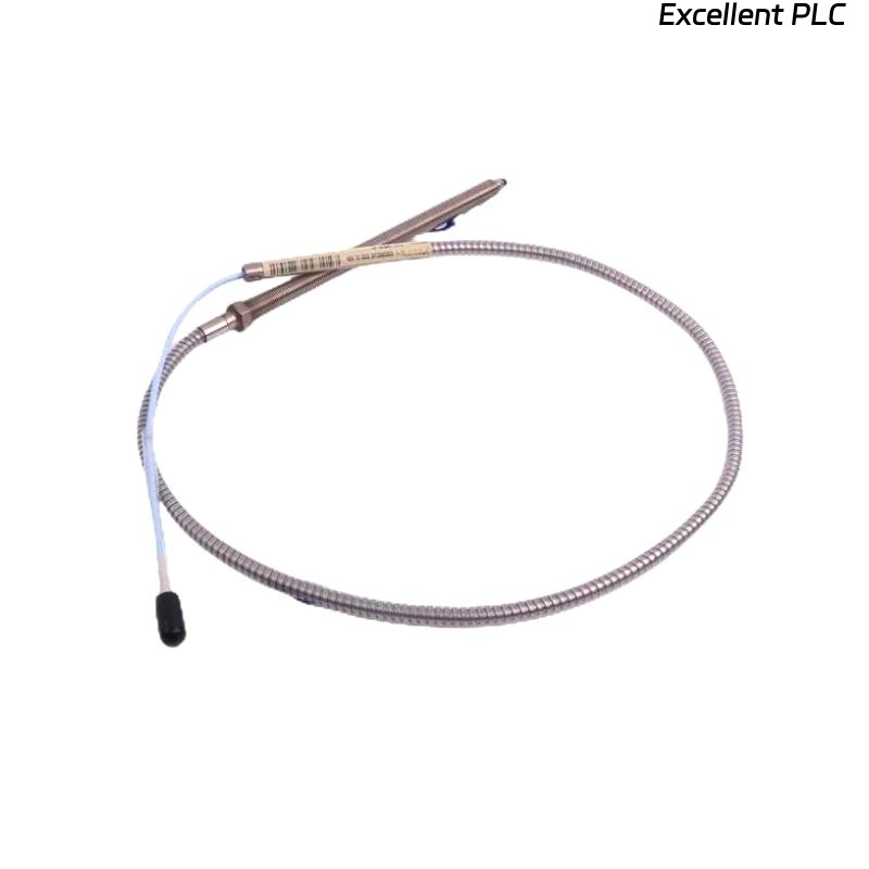
The Bently Nevada 109548-01 (P1407030-00100) is a 3300 XL NSv proximity probe designed for non-contact measurement of shaft displacement and vibration in rotating machinery. It is widely used in turbines, compressors, and motors for protection and condition monitoring.
Installation accuracy directly determines measurement reliability. Incorrect probe gap or mounting can lead to significant signal deviation or false alarms.
Working Principle of 109548-01 Proximity Probe
The probe operates using eddy current technology. It generates a high-frequency electromagnetic field, and the distance between the probe tip and shaft changes the impedance, which is converted into a vibration signal. :contentReference[oaicite:0]{index=0}
Pre-Installation Preparation
- Verify probe model and extension cable compatibility
- Check probe tip condition and insulation
- Confirm installation location (radial or axial measurement)
- Ensure clean and rigid mounting surface
Probe Mounting and Gap Adjustment
Proper gap setting is the most critical factor:
- Typical gap voltage: -8V to -10V
- Ensure probe perpendicular to shaft surface
- Avoid misalignment or eccentric installation
  // Gap Adjustment Logic
  Measure Output Voltage
  IF Voltage > -6V OR < -12V THEN
     Adjust Probe Position;
  END_IF;
Incorrect gap leads to non-linear measurement and reduced sensitivity.
Cable Installation and Shielding
- Use original extension cable (matched impedance)
- Avoid bending radius < 50 mm
- Separate from power cables (>300 mm)
- Shield grounding at monitor side only
Poor wiring can introduce noise and affect signal stability.
System Integration with 3300/3500
The probe is typically connected to:
- 3300 XL Proximitor sensor
- 3500 monitoring system
Ensure correct scaling (e.g., 200 mV/mil) and channel configuration.
Commissioning and Calibration
- Verify static gap voltage
- Compare with manual probe reading
- Check waveform stability during operation
Stable signal without drift confirms proper installation.
Field Installation Case
In a gas compressor system, the probe output showed unstable vibration signals.
- Gap voltage measured at -5V (incorrect)
- Probe slightly misaligned
After adjusting to -9V and correcting alignment, signal stabilized and matched analyzer data.
Installation FAQ
What is the correct gap voltage for Bently Nevada 109548-01?
The typical range is -8V to -10V. Outside this range, measurement accuracy decreases significantly.
Can the probe be installed at an angle?
No. The probe must be perpendicular to the shaft surface to ensure linear measurement.
Why is original extension cable required?
Because the system relies on matched impedance. Using non-original cables will cause calibration errors.
Final Recommendations
The Bently Nevada 109548-01 installation focuses on precise gap control, correct alignment, and proper system matching. These factors are critical for accurate shaft vibration monitoring and machinery protection.