

Table of Contents
- Bently Nevada 129715-064-028-05-05 Sensor Overview
- Application Scope of 129715-064-028-05-05
- Pre-Installation Preparation
- Mechanical Mounting and Alignment
- Signal Wiring and Shielding Guidelines
- Integration with 3500 Monitoring Modules
- Commissioning and Signal Verification
- Field Installation Case Study
- Installation FAQ
- Final Engineering Notes
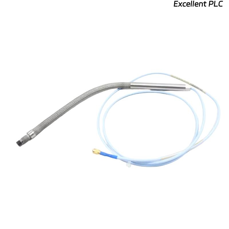
Bently Nevada 129715-064-028-05-05 Sensor Overview
The Bently Nevada 129715-064-028-05-05 is a precision proximity sensor for monitoring shaft displacement and vibration in industrial rotating machinery. Accurate installation ensures reliable condition monitoring and machinery protection.
Installation errors are the most common cause of false alarms or measurement errors rather than sensor defects.
Application Scope of 129715-064-028-05-05
- Steam turbines, gas turbines, and compressors
- Pumps, motors, and industrial gearboxes
- High-speed rotating equipment requiring continuous monitoring
- Integration with Bently Nevada 3500 monitoring modules for alarm management
Pre-Installation Preparation
- Verify sensor model and calibration certificate
- Inspect sensor tip, housing, and cable for physical damage
- Clean and prepare the mounting surface to be flat and rigid
- Prepare shielded twisted-pair signal cables for installation
Mechanical Mounting and Alignment
- Align probe axis precisely with the shaft measurement axis
- Torque mounting hardware per specification (6–8 Nm)
- Ensure correct tip-to-shaft clearance (typically 0.010–0.020 inches)
- Verify alignment using feeler gauges or calibration tool
  // Mounting Verification Logic
  IF Mounting_Surface_Not_Flat OR Tip_Clearance_Out_Of_Spec THEN
      Rework_Mounting;
  END_IF;
Signal Wiring and Shielding Guidelines
- Use twisted-pair shielded cable to maintain signal integrity
- Ground shield at one end only to avoid loops
- Route cables away from high-current lines and EMI sources
- Check continuity and insulation before connecting to 3500 module
Integration with 3500 Monitoring Modules
- Verify input type and scaling on the 3500/22 or 3500/23 module
- Set probe type and alarm thresholds in software
- Confirm signal logging and monitoring parameters
Commissioning and Signal Verification
- Power on the system and allow sensor warm-up
- Check baseline readings at machine idle
- Compare with portable vibration analyzer
- Monitor stability over at least 30 minutes
- Document readings for reference and verification
Field Installation Case Study
During a high-speed compressor installation, vibration readings were initially unstable due to slight misalignment and proximity to a power line. Realigning the probe and rerouting shielded cables corrected the readings, stabilizing measurements within ±0.05 mil.
Installation FAQ
Why do initial readings fluctuate?
Fluctuations are commonly caused by mechanical misalignment or EMI interference. Ensure proper probe alignment and cable shielding.
Can this sensor be used in high-temperature environments?
Yes, but always verify sensor and cable temperature ratings before installation.
How to verify correct tip-to-shaft clearance?
Use feeler gauges or system software to confirm distance is within the design specification.
Final Engineering Notes
Proper installation of Bently Nevada 129715-064-028-05-05 ensures precise vibration monitoring and reliable machinery protection. Attention to mechanical alignment, cable shielding, and system configuration is essential.