

Table of Contents
- 130118-0010-02 Installation Critical Points
- Installation Environment Requirements
- Probe Mounting Strategy
- Cable Routing and Shielding
- System Configuration and Setup
- Commissioning Verification Process
- Field Commissioning Case
- Installation FAQ
- Engineering Summary
130118-0010-02 Installation Critical Points
Bently Nevada 130118-0010-02 proximity probe installation errors are a primary source of unstable vibration signals and false alarms. In most commissioning cases, signal deviation is caused by incorrect probe gap or poor shielding rather than probe failure.
Installation Environment Requirements
- Ambient temperature within probe specification range
- No excessive vibration on mounting bracket
- Avoid installation near high-frequency drives (VFD)
- Proper grounding system available
Probe Mounting Strategy
- Ensure rigid mounting bracket to prevent secondary vibration
- Maintain probe gap typically between 0.5 mm – 2.0 mm depending on system
- Align probe perpendicular to shaft surface
- Avoid thermal expansion stress on probe body
  // Gap Adjustment Logic
  IF Output_Voltage NOT_IN Linear_Range THEN
      Adjust_Probe_Gap();
  END_IF;
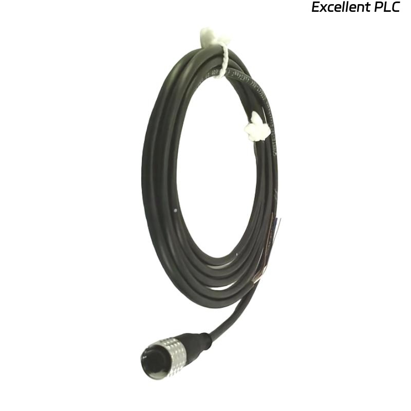
Cable Routing and Shielding
- Use factory-matched extension cable when applicable
- Keep signal cables at least 300 mm away from power cables
- Ground shield at monitor side only
- Avoid cable bending radius less than recommended minimum
System Configuration and Setup
- Configure probe type in Bently Nevada 3500 system
- Set alarm thresholds based on machine characteristics
- Verify scale factor (e.g., mV/mil)
- Ensure correct channel assignment
Commissioning Verification Process
- Power up and observe initial voltage (typically -8V to -10V range)
- Rotate shaft slowly and observe signal change
- Compare readings with portable vibration analyzer
- Run machine at rated speed and log data
Field Commissioning Case
In one compressor startup project, the 130118-0010-02 probe showed unstable readings during acceleration. Investigation revealed:
- Probe cable routed alongside motor power cable
- Shield grounded at both ends causing loop interference
After correcting grounding and rerouting cables, signal noise dropped by over 70%, and system stability improved significantly.
Installation FAQ
What is the correct initial voltage for setup?
Typically between -8V and -10V, depending on probe and extension cable combination.
Can I extend the cable length?
Only use specified extension cables. Unauthorized extension affects calibration and accuracy.
Why is probe alignment critical?
Misalignment causes nonlinear output and incorrect vibration readings.
Engineering Summary
The Bently Nevada 130118-0010-02 Installation Guide highlights that mechanical stability, proper gap setting, and correct shielding are essential for reliable monitoring. Accurate setup ensures stable data for condition-based maintenance systems.