

Table of Contents
- What is Bently Nevada 130539-17 Interconnect Cable
- Role of 130539-17 in Monitoring System
- Cable Installation Planning Strategy
- Cable Routing and Protection
- Termination and Connection Setup
- System Integration with Sensors & Modules
- Commissioning Validation
- Real Field Installation Case
- Installation FAQ
- Engineering Summary
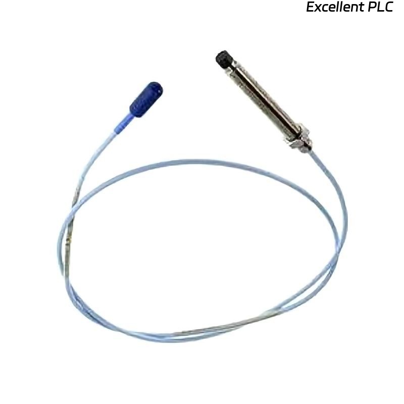
What is Bently Nevada 130539-17 Interconnect Cable
Bently Nevada 130539-17 is a 3-conductor shielded interconnect cable used to transmit vibration signals from accelerometers or proximity sensors to monitoring modules. Installation quality directly impacts signal integrity, especially in high-noise industrial environments. :contentReference[oaicite:0]{index=0}
Role of 130539-17 in Monitoring System
- Connects sensors such as 330400 accelerometers to monitoring racks
- Ensures stable signal transmission (DC to ~10 kHz range)
- Provides EMI protection via shielded 3-core structure
- Supports condition monitoring and protection systems
Cable Installation Planning Strategy
- Define cable route before installation (avoid rework)
- Separate signal and power cables (minimum 300 mm distance)
- Plan grounding scheme (single-point grounding)
- Check cable length (17 ft standard) to avoid tension or slack
Cable Routing and Protection
- Avoid routing near VFDs, transformers, or high-current feeders
- Use cable trays with EMI separation when possible
- Protect cable from mechanical stress and sharp edges
- Maintain bending radius >10× cable diameter
  // Cable Routing Rule
  IF Cable_Close_To_Power_Line THEN
      Increase_Distance OR Add_Shielding;
  END_IF;
Termination and Connection Setup
- Use factory 3-socket plug connection at sensor side
- Ensure terminal lugs are tightly secured at module side
- Verify no loose strands or improper crimping
- Apply shielding ground only at monitoring cabinet side
System Integration with Sensors & Modules
- Connect to Bently Nevada 3500 or similar monitoring system
- Verify channel mapping in system configuration
- Check compatibility with accelerometers or proximity systems
- Confirm signal scaling and input type
Commissioning Validation
- Power up system and verify signal continuity
- Check baseline vibration signal (e.g., 2–5 mm/s idle)
- Inspect noise level and waveform stability
- Run machine and monitor signal consistency
Real Field Installation Case
In a power plant retrofit project, engineers installed a 130539-17 cable parallel to a 6.6kV motor feeder. The vibration signal showed periodic spikes (~15 mm/s peak). After rerouting the cable and applying proper shielding:
- Noise reduced by ~65%
- Signal stabilized at 4.2 mm/s RMS
This confirmed that installation routing, not sensor fault, was the root cause.
Installation FAQ
Can this cable be extended?
Extension is not recommended unless calibrated. Additional length introduces attenuation and noise risk.
Why must shielding be grounded at one end?
Dual grounding creates ground loops, introducing noise into vibration signals.
What happens if routing is incorrect?
Signal distortion, false alarms, and inaccurate vibration readings will occur.
Engineering Summary
The Bently Nevada 130539-17 Installation Guide emphasizes routing discipline, shielding integrity, and proper termination. Cable installation quality is as critical as sensor accuracy in achieving reliable condition monitoring.