

Table of Contents
- Bently Nevada 131108-0025-01 Module Installation Entry
- Role of Position I/O Module in PLC and Monitoring Systems
- Integration Planning and Setup Strategy
- Module Installation and Wiring Execution
- Commissioning and Signal Validation
- Installation Best Practices for Stable Operation
- FAQ
- Technical Summary
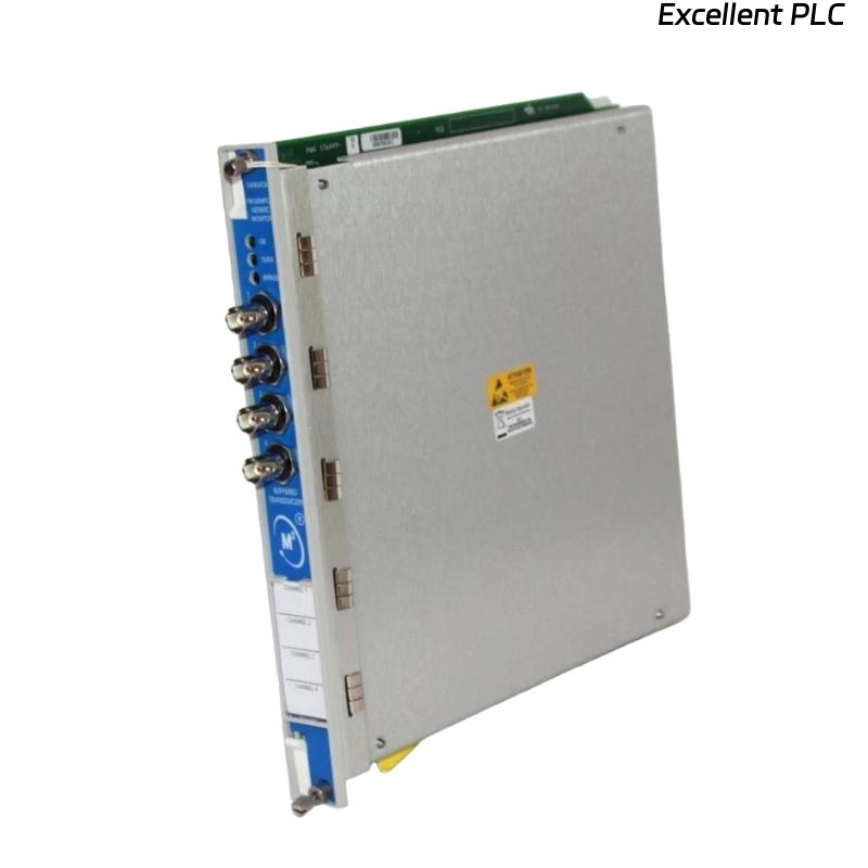
Bently Nevada 131108-0025-01 Module Installation Entry
Bently Nevada 131108-0025-01 position I/O module installation issues often result in incorrect position feedback rather than module failure. Misconfigured input channels or improper grounding can lead to unstable or offset signals.
This Installation Guide focuses on practical system configuration, wiring, and commissioning in real industrial environments.
Role of Position I/O Module in PLC and Monitoring Systems
The 131108-0025-01 module serves as a key interface between field sensors and control systems:
- Acquires position signals from proximity probes or displacement sensors
- Converts signals into process variables for PLC or monitoring modules
- Supports condition monitoring and protection logic
Accurate installation directly impacts fault diagnosis reliability.
Integration Planning and Setup Strategy
Before installation, define system-level configuration:
- Confirm sensor type (eddy current / LVDT / proximity)
- Check input signal range compatibility
- Verify rack slot allocation and module addressing
- Plan grounding architecture to avoid loops
Field Experience: In one retrofit project, incorrect signal range configuration caused 20% position deviation.
Module Installation and Wiring Execution
- Insert module into designated rack slot securely
- Connect sensor signal lines to input terminals
- Ensure correct polarity and shielding connection
- Link module output to PLC or monitoring system
Improper terminal wiring is a common source of commissioning delays.
Commissioning and Signal Validation
During commissioning, verify signal accuracy and stability:
- Measure input signal consistency (e.g., voltage or mA)
- Compare displayed position with actual mechanical displacement
- Simulate movement and observe system response
Real Case:
In a valve position monitoring system, a 5 mm offset was detected. After correcting wiring polarity, the deviation reduced to less than 0.5 mm.
Installation Best Practices for Stable Operation
- Use shielded cables for analog signals
- Separate signal and power wiring paths
- Document channel configuration for future troubleshooting
- Perform periodic calibration checks
FAQ
Why is the position reading inaccurate after installation?
This is usually due to incorrect wiring polarity or signal range mismatch.
Can this module connect directly to PLC?
Yes, but proper signal conditioning and configuration are required.
Is grounding important for position modules?
Yes, improper grounding can introduce noise and measurement errors.
Technical Summary
This Installation Guide shows that successful deployment of the Bently Nevada 131108-0025-01 position I/O module depends on proper system integration, accurate wiring, and thorough commissioning. Engineering-based setup ensures reliable signal acquisition for PLC systems and fault diagnosis.