

Table of Contents
- Bently Nevada 149776-01 Communication Module Installation Guide Entry
- Role of Fiber Optic Ethernet Module in Redundant Systems
- Network Topology Planning and Redundancy Strategy
- Hardware Installation and Fiber Connection
- System Configuration and Communication Setup
- Commissioning and Network Validation
- FAQ
- Technical Summary
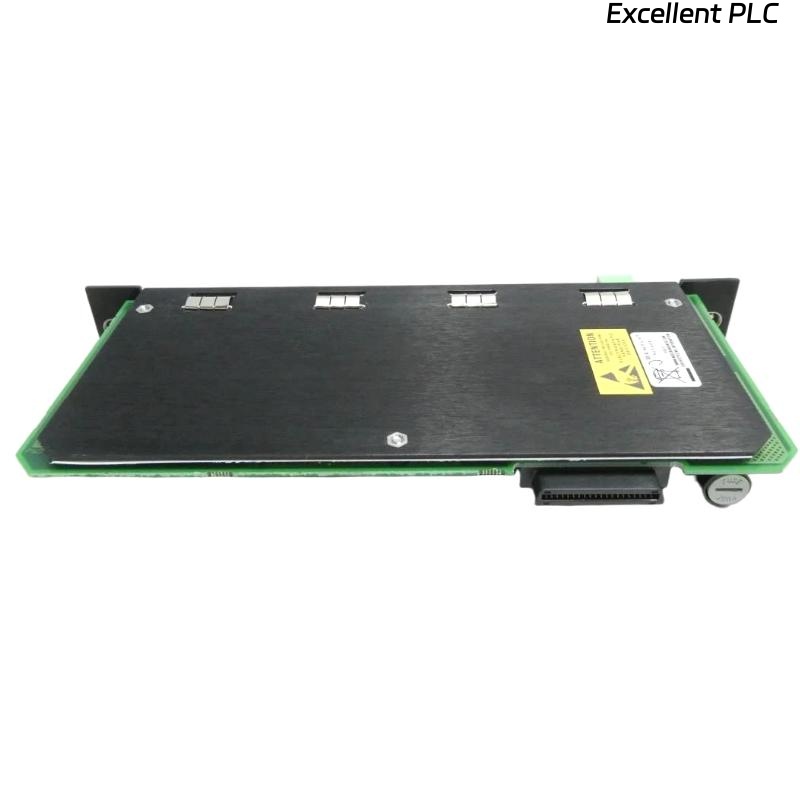
Bently Nevada 149776-01 Communication Module Installation Guide Entry
Bently Nevada 149776-01 fiber optic Ethernet communication module installation failures are frequently caused by incorrect network topology or improper fiber connections rather than module faults.
This Installation Guide focuses on redundant communication design, fiber handling, and commissioning practices for stable system operation.
Role of Fiber Optic Ethernet Module in Redundant Systems
- Provides high-speed Ethernet communication via fiber optics
- Supports redundant network architecture for reliability
- Used in critical monitoring systems requiring continuous data availability
It is essential for maintaining uninterrupted communication in industrial environments.
Network Topology Planning and Redundancy Strategy
- Define primary and backup communication paths
- Use ring or dual-network topology for redundancy
- Avoid single points of failure
- Ensure compatibility with system controllers and switches
Engineering Insight: Poor redundancy design can negate the advantages of fiber communication.
Hardware Installation and Fiber Connection
- Install module into designated rack slot
- Connect fiber optic cables (TX/RX correctly matched)
- Ensure connectors are clean and properly seated
- Secure cables to avoid bending or tension
Fiber handling requires precision to prevent signal loss.
System Configuration and Communication Setup
- Assign IP address and network parameters
- Configure redundancy settings
- Integrate with monitoring software or PLC system
IF module not detected:
    verify slot installation
    check power supply

IF no communication:
    check fiber TX/RX alignment
    verify IP configuration

IF redundancy not working:
    inspect network topology
    check switch configuration
Real Case:
In a compressor monitoring system, redundancy failed during testing. Investigation revealed incorrect fiber loop configuration. After correcting the topology, failover switching occurred within milliseconds.
Commissioning and Network Validation
- Test communication under normal and failover conditions
- Measure network latency and packet loss
- Verify automatic switching between primary and backup links
Successful commissioning ensures system reliability.
FAQ
Why is fiber polarity important?
Incorrect TX/RX connection will prevent communication.
How to ensure redundancy works correctly?
Test failover scenarios during commissioning.
Can dirty connectors affect performance?
Yes, contamination can cause signal attenuation or loss.
Technical Summary
This Installation Guide highlights that Bently Nevada 149776-01 fiber optic Ethernet modules require proper network design, precise fiber connections, and thorough commissioning. Correct setup ensures high reliability and redundancy in monitoring systems.