

Table of Contents
- Bently Nevada 168209-174-37-15-05-06 Installation Guide Entry
- 3300 XL 8 mm Probe Role in Precision Monitoring Systems
- Installation Strategy for High-Accuracy Measurement
- Gap Setting Method and Mechanical Stability
- Signal Integration and System Configuration
- Commissioning and Performance Verification
- FAQ
- Technical Summary
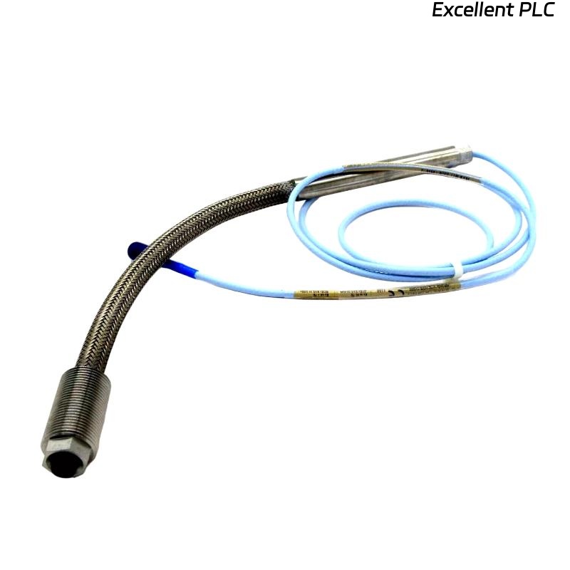
Bently Nevada 168209-174-37-15-05-06 Installation Guide Entry
Bently Nevada 168209-174-37-15-05-06 3300 XL 8 mm proximity probe installation inaccuracies are typically caused by improper gap setting and insufficient mounting rigidity, leading to unstable vibration data rather than probe malfunction.
This Installation Guide provides engineering-focused methods to ensure accurate displacement measurement and stable operation.
3300 XL 8 mm Probe Role in Precision Monitoring Systems
- Measures shaft vibration and position with high resolution
- Supports critical machinery protection systems
- Operates as part of a calibrated probe–extension–proximitor system
Installation precision directly affects measurement accuracy.
Installation Strategy for High-Accuracy Measurement
- Select rigid mounting location near bearing housing
- Ensure perpendicular alignment to shaft surface
- Avoid installation on flexible or resonant structures
- Consider thermal expansion during positioning
Field Insight: Even minor misalignment (<0.2 mm) can introduce signal distortion.
Gap Setting Method and Mechanical Stability
- Insert probe and approach shaft carefully
- Adjust probe to reach initial voltage range
- Lock position using double-nut method
- Re-check gap after tightening to avoid shift
Target gap voltage typically ranges between -8V and -10V.
Signal Integration and System Configuration
- Connect probe to compatible 3300 XL extension cable
- Verify proximitor calibration matches system length
- Ensure proper grounding and shielding continuity
IF voltage out of range:
    adjust probe gap
    verify proximitor calibration

IF signal unstable:
    check mounting rigidity
    inspect environmental vibration

IF no signal:
    verify full signal chain
    test cable continuity
Real Case:
In a centrifugal compressor system, vibration readings fluctuated between 6–10 mm/s. Gap voltage measured -6.5V, outside optimal range. After adjusting probe to achieve -9V, readings stabilized at 4 mm/s, aligning with expected machine condition.
Commissioning and Performance Verification
- Measure static and dynamic gap voltage
- Verify signal stability during startup and load changes
- Compare with baseline vibration data
Commissioning confirms installation quality and system readiness.
FAQ
What is the correct gap voltage for this probe?
Typically between -8V and -10V for optimal linear performance.
Why does vibration reading fluctuate after installation?
This is often due to improper gap setting or loose mounting.
Does system length affect probe performance?
Yes, mismatched system length impacts calibration and signal accuracy.
Technical Summary
This Installation Guide demonstrates that Bently Nevada 168209-174-37-15-05-06 probe performance depends on precise gap control, rigid mounting, and correct system configuration. Proper installation ensures reliable and accurate vibration monitoring.