

Table of Contents
- Bently Nevada 170180-02-00 Troubleshooting Entry
- 4–20 mA Signal Fault Symptoms
- Fault Diagnosis Method for Loop-Powered Systems
- Common Causes of Velocity Signal Failure
- Real Case: Loop Resistance Issue
- Recovery Strategy and Signal Optimization
- FAQ
- Technical Summary
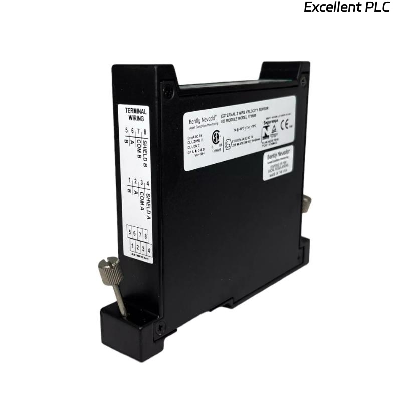
Bently Nevada 170180-02-00 Troubleshooting Entry
Bently Nevada 170180-02-00 external transducer I/O module troubleshooting shows that abnormal 4–20 mA signals—such as constant 4 mA, saturation at 20 mA, or unstable readings—are typically caused by loop wiring issues, power supply problems, or sensor faults rather than module failure.
This guide focuses on structured fault diagnosis for loop-powered vibration systems.
4–20 mA Signal Fault Symptoms
- Signal fixed at 4 mA (no output)
- Signal stuck at 20 mA (saturation)
- Fluctuating or noisy signal
- Intermittent signal loss
Each symptom reflects a specific loop or sensor issue.
Fault Diagnosis Method for Loop-Powered Systems
IF 4 mA constant:
    check loop continuity
    verify sensor power

IF 20 mA constant:
    check sensor saturation
    verify scaling configuration

IF unstable signal:
    inspect grounding
    check EMI sources

IF intermittent signal:
    inspect connectors
    measure loop voltage
This method isolates faults efficiently in industrial environments.
Common Causes of Velocity Signal Failure
- Excessive loop resistance reducing voltage
- Incorrect wiring polarity
- Power supply below required 24V DC
- Sensor internal failure or misalignment
Real Case: Loop Resistance Issue
In a refinery blower system, vibration signal fluctuated between 4–8 mA with no correlation to machine condition.
Observed Data:
- Loop voltage: 15V (should be ~24V)
- Cable length exceeded 200 meters
Root Cause: Excessive loop resistance causing insufficient sensor power.
Solution:
- Reduced cable length
- Improved power supply stability
Result: Signal stabilized between 6–14 mA and matched vibration levels.
Recovery Strategy and Signal Optimization
- Maintain proper loop voltage (24V DC)
- Limit cable resistance within design range
- Ensure correct wiring polarity
- Perform regular signal validation checks
Optimized loop design ensures stable monitoring.
FAQ
Why is the signal always 20 mA?
This indicates sensor saturation or scaling misconfiguration.
How to verify loop power?
Measure voltage across the loop; it should be close to 24V DC.
Is module replacement necessary?
No, most issues are related to wiring and loop conditions.
Technical Summary
This Troubleshooting Guide demonstrates that Bently Nevada 170180-02-00 module faults are primarily caused by loop wiring, power supply, and sensor issues. A structured fault diagnosis approach ensures reliable and stable vibration monitoring.