

Table of Contents
- Bently Nevada 173688-01-20-12-05 Installation Guide Entry
- Role of 3300 XL 8 mm Proximity Probe in Monitoring Systems
- Mechanical Installation and Target Alignment
- Electrical Matching with Cable and Proximitor
- Field Installation Risks and Mitigation
- Commissioning and Signal Verification
- FAQ
- Technical Summary
Bently Nevada 173688-01-20-12-05 Installation Guide Entry
Bently Nevada 173688-01-20-12-05 proximity probe installation problems are most frequently caused by incorrect gap setting or improper probe-to-target alignment rather than probe failure, leading to unstable or misleading vibration signals.
This Installation Guide focuses on correct probe positioning, system matching, and signal reliability.
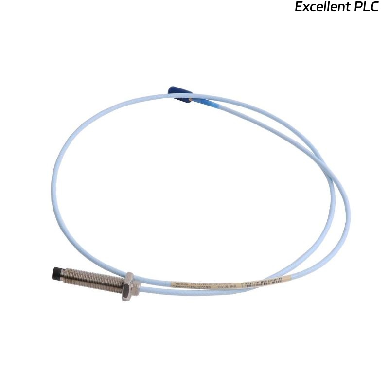
Role of 3300 XL 8 mm Proximity Probe in Monitoring Systems
- Measures shaft displacement and vibration using eddy current principle
- Provides high-resolution position feedback for rotating machinery
- Works with extension cable and proximitor as a complete system
Typical total system length (e.g., 9 meters) must match calibration for accurate output. :contentReference[oaicite:0]{index=0}
Mechanical Installation and Target Alignment
- Install probe perpendicular to shaft surface
- Ensure target surface is conductive and smooth
- Avoid mounting near edges or irregular surfaces
- Secure probe firmly to prevent movement under vibration
IF signal unstable:
    check probe alignment
    verify mounting rigidity

IF signal too low:
    probe not facing shaft correctly
Engineering Insight: Even a slight angular deviation (2–3°) can introduce waveform distortion.
Electrical Matching with Cable and Proximitor
- Must match system length (e.g., 5m or 9m system)
- Use compatible 3300 XL proximitor module
- Avoid mixing different series components
Critical Point: Probe, cable, and proximitor must be treated as one calibrated system.
Field Installation Risks and Mitigation
- Probe tip reading mounting bracket instead of shaft
- Loose installation causing gap drift
- Improper shielding introducing EMI noise
Real Case:
During compressor commissioning, vibration remained below 1 mm/s despite high load. Inspection revealed probe aimed at shaft sleeve instead of rotor. After repositioning, vibration reading corrected to 5.6 mm/s, matching expected condition.
Commissioning and Signal Verification
- Set gap voltage to -8V to -10V range
- Verify stable baseline voltage (~ -9V)
- Check signal during startup and load variation
IF voltage > -5V:
    probe too far

IF voltage < -12V:
    probe too close
Proper commissioning ensures accurate long-term monitoring.
FAQ
Why is the signal near zero?
This usually indicates incorrect probe alignment or wrong target surface.
Can probe and cable be mixed freely?
No, the system must match the calibrated length and type.
What is the ideal gap voltage?
Typically around -9V for optimal linear response.
Technical Summary
This Installation Guide shows that Bently Nevada 173688-01-20-12-05 probe performance depends on precise mechanical alignment, correct system configuration, and proper commissioning. Accurate setup ensures reliable shaft vibration and position monitoring.