

Table of Contents
- Bently Nevada 177230-00-01-CN Installation Guide Entry
- Role of Seismic Sensor in Hazardous Area Systems
- Mechanical Coupling Strategy for Accurate Vibration Transfer
- 4–20 mA Loop Design and System Configuration
- Installation Risks in Explosion-Proof Environments
- Commissioning and Signal Verification
- FAQ
- Technical Summary
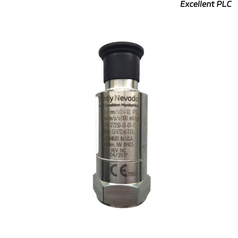
Bently Nevada 177230-00-01-CN Installation Guide Entry
Bently Nevada 177230-00-01-CN seismic sensor installation failures in hazardous areas are most commonly caused by improper mounting location or incorrect intrinsic safety wiring, leading to inaccurate vibration signals rather than transmitter failure.
This Installation Guide focuses on explosion-proof compliance, correct mechanical coupling, and stable 4–20 mA signal integration.
Role of Seismic Sensor in Hazardous Area Systems
- Measures casing vibration (velocity) in rotating equipment
- Outputs loop-powered 4–20 mA signal for PLC or monitoring module
- Certified for hazardous environments (ATEX / IECEx / CN approvals)
The CN version includes regional hazardous area certification, enabling safe installation in Zone environments. :contentReference[oaicite:0]{index=0}
Mechanical Coupling Strategy for Accurate Vibration Transfer
- Install directly on bearing housing or rigid structure
- Ensure flat mounting surface (Ra < 3.2 μm recommended)
- Use correct torque to ensure tight coupling
- Avoid mounting on covers, brackets, or thin plates
IF vibration too low:
    check mounting stiffness
    verify sensor position

IF inconsistent readings:
    inspect mechanical looseness
Engineering Insight: Seismic sensors depend entirely on structure-borne vibration; poor coupling reduces signal amplitude significantly.
4–20 mA Loop Design and System Configuration
- Loop-powered operation (typically 12–48 VDC)
- Output proportional to vibration velocity (e.g., 0–12.7 mm/s)
- Direct interface with PLC analog input or I/O module
Typical frequency response is 10 Hz to 1 kHz, suitable for general machinery monitoring. :contentReference[oaicite:1]{index=1}
IF 4 mA constant:
    check loop wiring
    verify sensor power

IF unstable current:
    inspect grounding
    check EMI interference
Installation Risks in Explosion-Proof Environments
- Incorrect grounding violating intrinsic safety requirements
- Improper cable gland sealing affecting IP rating
- Using non-certified accessories in hazardous zones
Real Case:
In a refinery compressor system, vibration signal fluctuated between 5–12 mA randomly. Investigation showed cable gland not properly sealed, allowing moisture ingress. After resealing and replacing connector, signal stabilized at 8–11 mA.
Commissioning and Signal Verification
- Verify baseline output (~4–6 mA at low vibration)
- Monitor response during startup and load change
- Cross-check with portable vibration analyzer
Commissioning ensures both safety compliance and measurement accuracy.
FAQ
What makes the CN version different?
It includes regional hazardous area certifications for use in explosion-proof environments.
Why is the signal lower than expected?
This is typically caused by poor mechanical coupling or incorrect mounting location.
Can it connect directly to a PLC?
Yes, via standard 4–20 mA analog input.
Technical Summary
This Installation Guide shows that Bently Nevada 177230-00-01-CN sensor performance depends on proper mechanical coupling, compliant hazardous area installation, and stable current loop configuration. Correct setup ensures reliable vibration monitoring in critical industrial environments.