

Table of Contents
- Bently Nevada 170180-01-05 Installation Guide Entry
- Role of External Transducer I/O Module in FieldMonitor Systems
- Signal Architecture and Input Strategy
- Sensor Wiring and Channel Assignment
- Environmental and Power Requirements
- System Validation and Commissioning
- FAQ
- Technical Summary
Bently Nevada 170180-01-05 Installation Guide Entry
Bently Nevada 170180-01-05 external transducer I/O module installation problems are most commonly caused by incorrect sensor type connection or improper channel configuration, leading to signal distortion rather than actual module failure.
This Installation Guide focuses on proper signal integration, wiring discipline, and reliable system configuration in FieldMonitor environments.
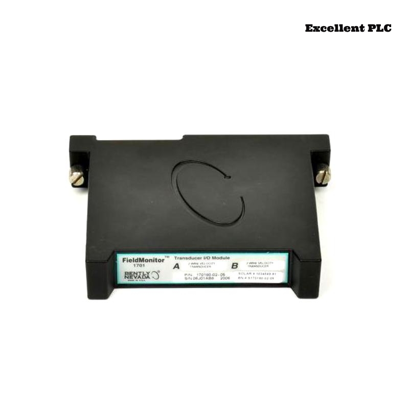
Role of External Transducer I/O Module in FieldMonitor Systems
- Interfaces proximity probes, velocity sensors, and accelerometers
- Supports dual-channel input per module
- Transfers conditioned signals to monitoring modules and PLC systems
The module acts as a bridge between field sensors and the monitoring system architecture. :contentReference[oaicite:0]{index=0}
Signal Architecture and Input Strategy
- Sensor → I/O Module → Monitor → PLC / Control System
- Supports mixed transducer types with proper configuration
- Typical system frequency response up to 50 kHz
Engineering Insight: Mixing velocity and proximity signals without proper scaling causes misleading vibration trends.
Sensor Wiring and Channel Assignment
- Assign sensors to Channel A / B based on measurement priority
- Verify sensor output type (e.g., mV, -24V proximitor signal)
- Use shielded twisted pair cables
- Ground shielding at one end only to prevent loops
IF no signal:
    verify sensor power supply
    check wiring continuity

IF incorrect readings:
    confirm sensor type vs configuration
    verify scaling parameters

IF intermittent signal:
    inspect connector integrity
    check terminal tightness
Real Case:
During commissioning of a centrifugal pump, Channel A displayed stable 3.2 mm/s, while Channel B showed intermittent spikes up to 12 mm/s. Investigation revealed shared grounding between signal and power lines. After isolating grounding and rerouting cables, signal stabilized at 3.5 mm/s.
Environmental and Power Requirements
- Operating temperature: -40°C to +70°C
- Power consumption: ≤1.5W
- IP67 protection for harsh environments
These characteristics allow reliable operation in industrial environments. :contentReference[oaicite:1]{index=1}
System Validation and Commissioning
- Verify signal stability under machine startup
- Compare readings with handheld vibration analyzer
- Confirm correct data transmission to PLC or monitoring system
Commissioning ensures full system reliability.
FAQ
Can different sensor types be connected simultaneously?
Yes, but each channel must be correctly configured for the specific sensor type.
Why does one channel show unstable readings?
This is usually caused by grounding issues or incorrect wiring.
What is the most common installation mistake?
Mixing signal types or incorrect shielding connection.
Technical Summary
This Installation Guide emphasizes that Bently Nevada 170180-01-05 module performance depends on proper wiring, correct sensor configuration, and stable grounding. Accurate installation ensures reliable multi-sensor monitoring in FieldMonitor systems.