

Table of Contents
- Bently Nevada 177230-01-01-CN Installation Guide Entry
- Role of 177230 Seismic Sensor in Hazardous Area Monitoring
- Engineering-Based Mounting Method
- 4–20 mA Loop Configuration and PLC Integration
- Environmental and Certification Risks
- Commissioning Strategy and Validation
- FAQ
- Technical Summary
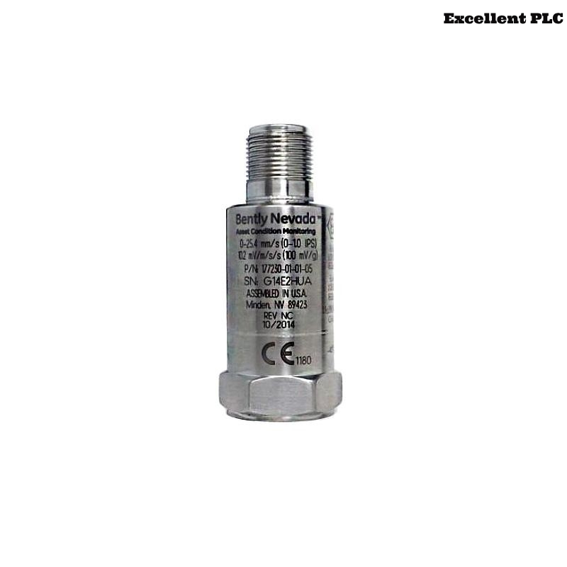
Bently Nevada 177230-01-01-CN Installation Guide Entry
Bently Nevada 177230-01-01-CN seismic sensor installation errors are most commonly caused by improper mounting stiffness or incorrect intrinsic safety loop wiring, leading to distorted 4–20 mA signals rather than actual sensor failure.
This Installation Guide focuses on hazardous area compliance, vibration transmission integrity, and stable system configuration.
Role of 177230 Seismic Sensor in Hazardous Area Monitoring
- Measures casing vibration (velocity) for rotating equipment
- Outputs 4–20 mA signal for PLC or I/O Module integration
- Certified for hazardous environments (CN / ATEX / IECEx)
The sensor operates typically in the 10 Hz to 1 kHz frequency range and supports vibration measurement up to 25.4 mm/s, suitable for industrial machinery monitoring. :contentReference[oaicite:0]{index=0}
Engineering-Based Mounting Method
Installation must be treated as a vibration transmission system rather than a simple sensor mounting task.
- Select rigid mounting location (bearing housing preferred)
- Prepare flat metal surface (remove paint or corrosion)
- Install using 1/4-28 UNF threaded stud
- Apply proper torque to ensure tight coupling
IF output signal too low:
    vibration not effectively transmitted

IF signal unstable:
    mounting looseness or surface issue
Engineering Insight: Even high-quality sensors cannot compensate for poor mechanical coupling.
4–20 mA Loop Configuration and PLC Integration
- Loop-powered (typically 9–32 VDC)
- Output: 4–20 mA proportional to vibration velocity
- Direct interface with PLC analog input modules
IF no current:
    check loop continuity
    verify power supply

IF signal stuck at 4 mA:
    no vibration or installation issue

IF fluctuating signal:
    check grounding and EMI
Correct wiring ensures stable signal transmission into control systems.
Environmental and Certification Risks
- Improper cable gland sealing (IP67 violation)
- Incorrect intrinsic safety barrier wiring
- Using non-certified accessories in hazardous zones
The sensor features stainless steel housing and IP67 protection, designed for harsh environments. :contentReference[oaicite:1]{index=1}
Real Case:
In a petrochemical compressor unit, vibration signal fluctuated between 6–15 mA during operation.
Observed:
- Signal instability increased with humidity
- No mechanical vibration change
Root Cause: Improper sealing caused moisture ingress into connector.
Solution:
- Replaced connector and gland
- Applied certified sealing method
Result: Signal stabilized at 9–11 mA with consistent vibration values.
Commissioning Strategy and Validation
- Verify baseline current (~4–6 mA at low vibration)
- Monitor signal during startup ramp
- Cross-check with portable vibration analyzer
Field Tip: Commissioning should be done after thermal stabilization to avoid false readings.
FAQ
What does the CN suffix indicate?
It represents country-specific hazardous area certifications such as ATEX, IECEx, or regional approvals.
Why is vibration reading unstable?
This is usually caused by moisture ingress, grounding issues, or EMI interference.
Can this sensor connect directly to a PLC?
Yes, via standard 4–20 mA analog input modules.
Technical Summary
This Installation Guide highlights that Bently Nevada 177230-01-01-CN performance depends on proper mechanical coupling, compliant hazardous area installation, and stable loop configuration. Correct setup ensures accurate and reliable vibration monitoring in critical industrial environments.