

Table of Contents
- Bently Nevada 177230-01-02-05 Installation Guide Entry
- Impact of Measurement Range on Installation Strategy
- Mechanical Installation Path and Energy Transfer
- System Wiring and PLC Integration
- Critical Installation Mistakes in High-Range Applications
- Verification and Commissioning Workflow
- FAQ
- Technical Summary
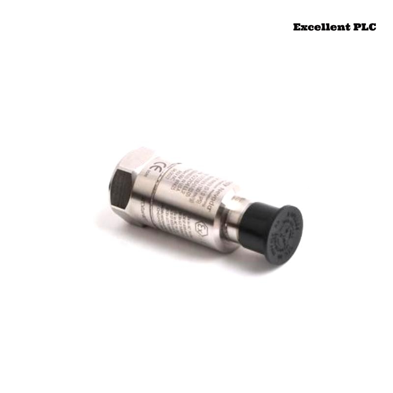
Bently Nevada 177230-01-02-05 Installation Guide Entry
Bently Nevada 177230-01-02-05 seismic sensor installation problems are frequently linked to incorrect mounting strategy for high-range vibration measurement, resulting in signal compression or under-reporting rather than sensor malfunction.
This Installation Guide emphasizes correct installation for extended vibration range applications and accurate 4–20 mA signal scaling.
Impact of Measurement Range on Installation Strategy
The 177230-01-02-05 model typically supports a higher vibration range (e.g., up to ~50.8 mm/s), which changes installation requirements significantly.
- Higher range requires stronger mechanical coupling
- Mounting location must capture full vibration amplitude
- Signal scaling must match PLC configuration
Engineering Insight: Incorrect installation can compress the usable signal range, making faults harder to detect. :contentReference[oaicite:0]{index=0}
Mechanical Installation Path and Energy Transfer
The installation should follow vibration transmission physics:
- Source vibration (bearing housing)
- Transmission surface (metal interface)
- Sensor coupling (thread + torque)
- Internal signal conversion
IF signal amplitude too low:
    vibration energy lost at interface

IF signal clipped:
    wrong measurement range or installation point
Key Requirement: Install directly on rigid structural components, not auxiliary covers.
System Wiring and PLC Integration
- Loop-powered system (12–48 VDC typical)
- Output: 4–20 mA proportional to vibration velocity
- Compatible with PLC, DCS, and monitoring modules
IF no signal:
    check loop continuity

IF signal stuck near 4 mA:
    insufficient vibration or installation issue

IF signal saturates early:
    PLC scaling mismatch
The sensor provides stable industrial performance with IP67 protection and wide environmental tolerance. :contentReference[oaicite:1]{index=1}
Critical Installation Mistakes in High-Range Applications
- Installing sensor on low-vibration zones
- Incorrect PLC scaling (e.g., using low-range configuration)
- Loose mounting causing signal damping
Real Case:
In a large centrifugal compressor, vibration peaks were expected above 20 mm/s, but system readings stayed below 10 mA.
Observed:
- Signal did not increase proportionally with load
Root Cause: PLC scaling configured for 0–12.7 mm/s instead of high-range sensor.
Solution:
- Updated PLC scaling to match sensor range
Result: Signal range corrected (8–18 mA), matching real vibration (~22 mm/s).
Verification and Commissioning Workflow
- Check baseline output (~4–6 mA)
- Simulate vibration increase (load ramp)
- Validate scaling with reference analyzer
Commissioning Tip: Always verify both mechanical installation and PLC scaling simultaneously.
FAQ
Why does the signal not reach 20 mA?
This may be caused by incorrect PLC scaling or insufficient vibration amplitude.
How to confirm correct measurement range?
Check model configuration and compare with system scaling settings.
Can this sensor detect low vibration accurately?
Yes, but sensitivity depends on correct mounting and configuration.
Technical Summary
This Installation Guide highlights that Bently Nevada 177230-01-02-05 performance depends on proper installation for high-range vibration, correct PLC scaling, and stable loop configuration. Accurate setup ensures reliable monitoring of high-energy machinery.