

Table of Contents
- Bently Nevada 177230-01-02-CN Installation Guide Entry
- System Context of 177230 Seismic Sensor in Hazardous Areas
- Mechanical Integrity and Vibration Capture Strategy
- 4–20 mA Signal Loop and System Configuration
- Hazardous Area Installation Risks and Compliance
- Commissioning Workflow and Data Validation
- FAQ
- Technical Summary
Bently Nevada 177230-01-02-CN Installation Guide Entry
Bently Nevada 177230-01-02-CN seismic sensor installation issues are most often caused by incorrect mounting location or improper hazardous area wiring, resulting in distorted 4–20 mA output rather than sensor malfunction.
This Installation Guide focuses on high-reliability installation in hazardous environments and accurate vibration signal transmission.
System Context of 177230 Seismic Sensor in Hazardous Areas
- Measures casing vibration velocity for rotating equipment
- Provides loop-powered 4–20 mA output
- Certified for hazardous environments (CN approvals)
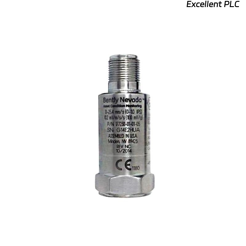
The sensor typically supports vibration ranges such as 0–25.4 mm/s with frequency response around 3 Hz to 1 kHz, suitable for industrial machinery monitoring. :contentReference[oaicite:0]{index=0}
Engineering Note: In hazardous areas, installation quality directly impacts both measurement accuracy and safety compliance.
Mechanical Integrity and Vibration Capture Strategy
Installation must ensure full vibration energy transfer from machine structure to sensor:
- Select rigid mounting point (bearing housing preferred)
- Ensure clean, metallic contact surface
- Use correct 1/4-28 UNF mounting thread
- Apply proper torque to eliminate micro-gaps
IF vibration signal low:
    energy loss at mounting interface

IF signal unstable:
    mounting looseness or structural resonance
Engineering Insight: Poor mechanical coupling reduces signal amplitude more than 30% in some field cases.
4–20 mA Signal Loop and System Configuration
- Power supply: typically 12–36 VDC
- Output: 4–20 mA proportional to vibration velocity
- Integration: PLC / DCS analog input modules
IF loop current = 0:
    check wiring continuity
    verify power source

IF constant 4 mA:
    no vibration or installation issue

IF noisy signal:
    check grounding and EMI
Stable loop configuration is essential for accurate vibration monitoring.
Hazardous Area Installation Risks and Compliance
- Improper intrinsic safety barrier configuration
- Incorrect cable gland sealing affecting IP rating
- Use of non-certified accessories
The sensor uses stainless steel housing and IP67 protection for harsh environments. :contentReference[oaicite:1]{index=1}
Real Case:
In a petrochemical plant, vibration signals fluctuated between 5–14 mA during stable operation.
Observed:
- Signal variation correlated with ambient humidity
Root Cause: Moisture ingress due to improper cable gland sealing.
Solution:
- Replaced gland with certified sealing component
- Improved enclosure sealing
Result: Signal stabilized at 8–10 mA with consistent vibration readings.
Commissioning Workflow and Data Validation
- Verify baseline output (~4–6 mA)
- Monitor signal during machine startup
- Cross-check with portable vibration analyzer
Commissioning Tip: Perform validation after thermal stabilization to avoid false readings.
FAQ
What does CN mean in the model?
It indicates country-specific hazardous area certifications.
Why is the signal unstable in humid environments?
This is usually caused by moisture ingress affecting connectors or wiring.
Can it connect directly to a PLC?
Yes, via standard 4–20 mA analog input.
Technical Summary
This Installation Guide shows that Bently Nevada 177230-01-02-CN performance depends on proper mechanical coupling, compliant hazardous area installation, and stable current loop configuration. Correct setup ensures reliable vibration monitoring in industrial environments.