

Table of Contents
- Bently Nevada 177230-02-01-05 Installation Guide Entry
- Role of 177230-02-01-05 Seismic Sensor in PLC Monitoring Systems
- Mechanical Installation Strategy for High-Range Sensors
- 4–20 mA Loop Wiring and System Configuration
- Engineering Risks in Hazardous and High-Vibration Environments
- Commissioning and Validation Process
- FAQ
- Technical Summary
Bently Nevada 177230-02-01-05 Installation Guide Entry
Bently Nevada 177230-02-01-05 seismic sensor installation errors are most often caused by incorrect mounting stiffness or mismatch between sensor range and PLC scaling, leading to signal distortion instead of actual sensor failure.
This Installation Guide focuses on high-range vibration monitoring systems where accurate mechanical coupling and correct system configuration are critical.
Role of 177230-02-01-05 Seismic Sensor in PLC Monitoring Systems
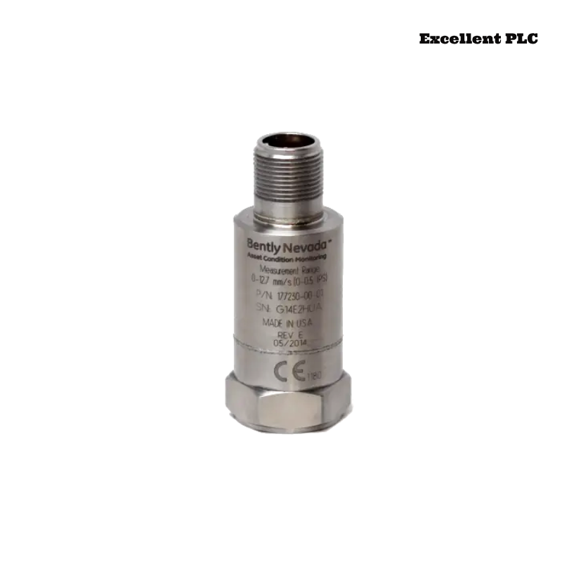
- Measures casing vibration velocity (high range)
- Outputs 4–20 mA loop-powered signal
- Supports PLC, DCS, and SCADA integration
- Includes dynamic signal output for advanced diagnostics
The sensor typically supports up to 50.8 mm/s vibration range with frequency response from ~10 Hz to 1 kHz, suitable for heavy rotating equipment. :contentReference[oaicite:0]{index=0}
Mechanical Installation Strategy for High-Range Sensors
High-range seismic sensors require stricter mechanical installation compared to standard models:
- Install on rigid bearing housing (avoid brackets or covers)
- Remove paint and oxidation to ensure metal contact
- Use 1/4-28 UNF stud with correct torque
- Avoid locations with structural damping
IF signal amplitude too low:
    vibration energy lost at mounting interface

IF signal clipped:
    sensor not installed at vibration peak location
Engineering Insight: At vibration levels above 30 mm/s, even slight mounting looseness can introduce >20% measurement error.
4–20 mA Loop Wiring and System Configuration
- Supply voltage: typically 24 VDC (±20%)
- Output: 4–20 mA proportional to vibration velocity
- Optional dynamic signal output for advanced diagnostics
IF loop current = 0:
    check power supply and wiring continuity

IF signal stuck at 4 mA:
    installation or vibration transmission issue

IF signal saturates early:
    PLC scaling mismatch
The sensor is loop-powered and designed for easy integration into existing control systems without complex configuration. :contentReference[oaicite:1]{index=1}
Engineering Risks in Hazardous and High-Vibration Environments
- Incorrect intrinsic safety barrier wiring
- Improper cable shielding causing EMI
- Mounting on low-energy vibration zones
- Scaling mismatch between sensor and PLC
Real Case:
In a gas turbine system, vibration readings remained below 12 mA during full load operation.
Observed Data:
- Expected vibration ~28 mm/s
- Signal did not exceed mid-range
Root Cause: Sensor installed on structural support with low vibration transmission.
Solution:
- Relocated to bearing housing
- Re-validated mounting torque
Result: Signal increased to 9–18 mA, matching actual vibration levels.
Commissioning and Validation Process
- Verify baseline (~4–6 mA at idle condition)
- Monitor signal across load ramp
- Compare with portable vibration analyzer
Field Tip: Always validate both installation and PLC scaling during commissioning.
FAQ
Why does the signal not reach 20 mA?
This is usually due to incorrect PLC scaling or installation at a low vibration location.
What is the measurement range of this model?
Typically up to 50.8 mm/s (high-range seismic monitoring). :contentReference[oaicite:2]{index=2}
Can it be used in hazardous environments?
Yes, this model supports multiple approvals such as ATEX and IECEx. :contentReference[oaicite:3]{index=3}
Technical Summary
This Installation Guide demonstrates that Bently Nevada 177230-02-01-05 performance depends on proper high-rigidity mounting, correct PLC scaling, and stable loop configuration. Accurate installation ensures reliable monitoring in high-energy rotating machinery.