

Bently Nevada 1900/27-02-00 Vibration Monitor Installation Guide Using Reverse Commissioning Method for System Configuration
Table of Contents
- When Commissioning Fails Even After “Correct” Installation
- Observed Problems in 1900/27-02-00 Startup Phase
- Why We Started Debugging Instead of Reinstalling
- Reconstructing Installation Logic from Signal Behavior
- Correct System Configuration Strategy
- Final Validation Using Real Operating Data
- 1900/27-02-00 Installation Best Practices
- FAQ
- Technical Summary
When Commissioning Fails Even After “Correct” Installation
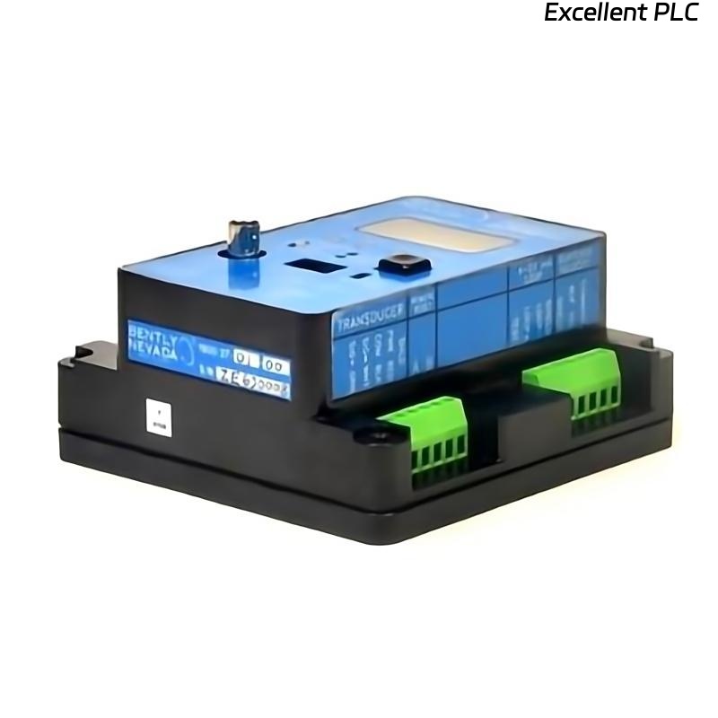
Bently Nevada 1900/27-02-00 vibration monitor installation issues are often discovered only during commissioning. The system powers up normally, wiring checks pass, but the behavior under real operation is inconsistent.
In practice, installation is often declared “complete” too early — before signal behavior is verified.
Observed Problems in 1900/27-02-00 Startup Phase
During startup of a centrifugal pump system, we observed:
- Displayed vibration jumps during acceleration
- Stable reading at idle but unstable under load
- No corresponding mechanical abnormality
The system passed installation inspection, yet clearly failed in operation.
Why We Started Debugging Instead of Reinstalling
Instead of removing wiring, we treated commissioning data as diagnostic input.
This approach is critical:
installation quality is judged by signal behavior, not by checklist completion.
Reconstructing Installation Logic from Signal Behavior
We analyzed the signal characteristics:
- Signal amplitude increased disproportionately with load
- Noise appeared only when nearby VFD activated
IF signal_instability correlates_with_load:
    CHECK EMI influence

IF baseline stable but dynamic unstable:
    CHECK signal routing
This pointed us to installation-related interference rather than configuration error alone.
Correct System Configuration Strategy
After isolating the issue, we corrected both installation and configuration:
- Separated signal cable from inverter output line (>30 cm)
- Re-grounded shield at single point
- Verified correct sensor input type in monitor
- Adjusted scaling to match sensor output
Important note:
configuration alone could not fix the issue — physical installation had to be corrected first.
Final Validation Using Real Operating Data
After correction, validation focused on dynamic behavior:
- Startup curve became smooth
- No spikes during load transitions
- Voltage signal stable within ±0.3V equivalent
We repeated startup 4 times to confirm consistency.
1900/27-02-00 Installation Best Practices
- Do not finalize installation before dynamic testing
- Use commissioning data to validate installation quality
- Always consider EMI in modern VFD environments
- Ensure configuration matches actual sensor characteristics
FAQ
Why does 1900/27-02-00 show unstable readings only during startup?
This is typically caused by electromagnetic interference or improper cable routing under dynamic load conditions.
Is it necessary to re-install hardware when commissioning fails?
Not always. Analyzing signal behavior often reveals specific installation issues that can be corrected without full reinstallation.
Technical Summary
Bently Nevada 1900/27-02-00 installation must be validated through real operating conditions rather than static checks. Field experience shows that many installation issues only appear during dynamic operation. Using reverse commissioning logic allows engineers to identify and correct hidden installation defects efficiently, ensuring reliable vibration monitoring performance.