

Table of Contents
- Bently Nevada 200355-01-00-00 Accelerometer Installation Overview
- Installation Planning for 200355 Accelerometer System
- Mechanical Mounting and Coupling Strategy
- Electrical Wiring and Shielding Design
- System Integration and PLC Configuration
- Commissioning Workflow and Signal Validation
- Real Field Installation Case
- Installation FAQ
- Final Engineering Summary
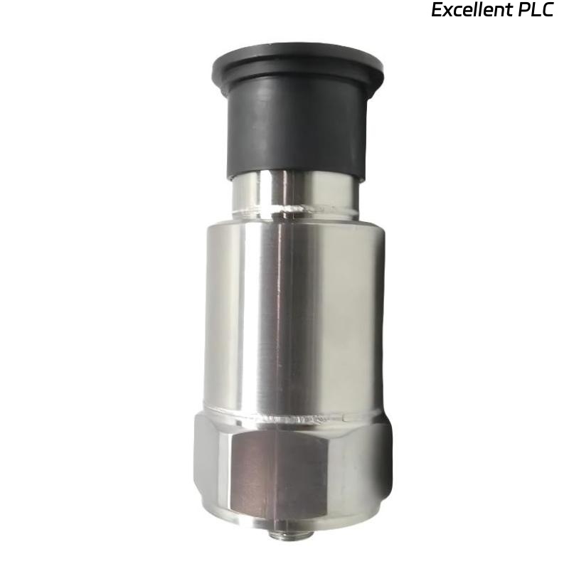
Bently Nevada 200355-01-00-00 Accelerometer Installation Overview
Bently Nevada 200355-01-00-00 accelerometer Installation Guide shows that incorrect installation leads to misleading vibration data rather than total signal failure. In field commissioning, engineers often misjudge machine condition due to poor sensor setup instead of real mechanical faults.
This guide focuses on proper setup, wiring integrity, and commissioning to ensure accurate data acquisition in industrial vibration monitoring systems.
Installation Planning for 200355 Accelerometer System
- Identify critical measurement points (bearing housing preferred)
- Define monitoring direction (horizontal / vertical / axial)
- Evaluate environmental factors (temperature, oil, vibration)
- Ensure compatibility with PLC Controller or monitoring module
Mechanical Mounting and Coupling Strategy
- Use threaded stud mounting for permanent installation
- Ensure direct metal contact (remove paint and debris)
- Mount on rigid machine structure, not covers
- Apply consistent torque to prevent loosening
  // Mounting Decision Logic
  IF Mount_Location = Flexible THEN
      Reject_Installation();
  ELSE
      Approve_Mounting();
  END_IF;
Electrical Wiring and Shielding Design
- Use industrial shielded cable for low-noise transmission
- Ground shielding at one side only
- Separate signal cable from power cable routes
- Protect connectors from moisture and contamination
System Integration and PLC Configuration
- Configure input type (IEPE accelerometer)
- Set sensitivity (e.g., 100 mV/g typical)
- Define alarm thresholds based on machine baseline
- Verify scaling (acceleration to velocity if required)
Commissioning Workflow and Signal Validation
- Measure bias voltage (~10 VDC typical)
- Record baseline vibration values (1–4 mm/s typical)
- Analyze FFT spectrum for abnormal peaks
- Verify repeatability across operating cycles
Real Field Installation Case
During commissioning of a centrifugal fan system, high vibration alarms were reported:
- Measured: 10.1 mm/s RMS
- Machine condition: visually stable
We observed the sensor was mounted on a support bracket instead of the bearing housing.
After correction:
- Relocated sensor to bearing housing
- Improved cable routing
Result:
- Vibration reduced to 3.6 mm/s
- System operated without false alarms
Installation FAQ
Where is the best mounting location for the accelerometer?
Always on rigid structures such as bearing housings for accurate vibration transmission.
Why is shielding important in installation?
Proper shielding prevents EMI interference that can distort vibration signals.
What is the most common installation mistake?
Mounting on flexible surfaces or incorrect locations.
Final Engineering Summary
The Bently Nevada 200355-01-00-00 Installation Guide emphasizes correct mechanical mounting and signal integrity as key factors. Proper system configuration ensures accurate and reliable vibration monitoring.