

Yokogawa SB401-53 ESB Bus Interface Slave Module installation issues are often caused by ESB network configuration errors, improper node assignments, or communication topology mismatches rather than module defects. A structured Installation Guide helps ensure reliable ESB communication, stable data exchange, and successful system commissioning within Yokogawa CENTUM VP and ProSafe-RS architectures. The SB401-53 functions as an ESB Bus Interface Slave Module supporting high-speed communication and redundant ESB bus configurations. :contentReference[oaicite:0]{index=0}
Contents
- SB401-53 ESB Bus Interface Slave Module Overview
- Purpose of the SB401-53 Module
- ESB Network Topology Planning
- Installation Requirements
- Module Inspection Before Installation
- Environmental Verification
- Node Unit Preparation
- Power Verification
- SB401-53 Installation Guide
- ESB Bus Connection Procedure
- SB401-53 Setup Procedure
- System Configuration Validation
- Redundant ESB Configuration
- Commissioning Verification
- Communication Performance Testing
- Maintenance Recommendations
- Real Commissioning Case
- FAQ
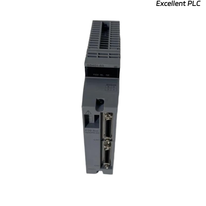
SB401-53 ESB Bus Interface Slave Module Overview
The Yokogawa SB401-53 is an ESB Bus Interface Slave Module designed to connect field control stations and distributed node units through Yokogawa ESB communication architecture. It supports high-speed cyclic data transmission and redundant network operation. :contentReference[oaicite:1]{index=1}
Purpose of the SB401-53 Module
- ESB bus communication management
- Distributed I/O connectivity
- Data synchronization
- Controller communication support
- Redundant network operation
ESB Network Topology Planning
- Single ESB architecture
- Dual redundant ESB design
- Node address allocation
- Communication path planning
- Bus load evaluation
Installation Requirements
- Approved engineering database
- Compatible node unit
- Verified controller configuration
- Network documentation
- Communication test procedures
Module Inspection Before Installation
- Verify model number
- Inspect connectors
- Check module housing
- Review hardware revision
- Inspect backplane contacts
Environmental Verification
- Cabinet temperature control
- Humidity monitoring
- EMC protection
- Grounding verification
- Ventilation assessment
Node Unit Preparation
- Verify node unit type
- Check slot allocation
- Inspect terminal assemblies
- Validate mounting hardware
Power Verification
- Confirm power availability
- Verify power redundancy
- Inspect grounding continuity
- Review power quality records
SB401-53 Installation Guide
- Isolate cabinet power.
- Insert the SB401-53 module into the designated slot.
- Lock the module securely.
- Connect ESB communication cables.
- Verify mechanical seating.
- Inspect status indicators after startup.
ESB Bus Connection Procedure
- Verify bus routing
- Confirm connector orientation
- Check cable labeling
- Inspect termination arrangements
- Validate communication continuity
SB401-53 Setup Procedure
INSTALL MODULE
VERIFY NODE STATUS
CONFIGURE ESB PARAMETERS
DOWNLOAD DATABASE
ENABLE COMMUNICATION
SAVE CONFIGURATION
RESTART NODE
System Configuration Validation
- Node assignment verification
- Address validation
- Communication parameter review
- I/O allocation confirmation
- Database consistency checks
Redundant ESB Configuration
- Primary path verification
- Backup path testing
- Redundancy switching validation
- Communication recovery checks
Commissioning Verification
- Node communication tests
- I/O update verification
- Alarm monitoring
- Diagnostic review
- Integrated system testing
Communication Performance Testing
- Data update verification
- Network latency analysis
- Communication error review
- Redundant path validation
Maintenance Recommendations
- Periodic diagnostics review
- Database backup
- Cable inspection
- Network health monitoring
Real Commissioning Case
During commissioning of a refinery expansion project, a newly installed SB401-53 failed to establish communication with the field node network.
- Power Status: Normal
- Module Status: Online
- Communication Status: Offline
- I/O Update Status: Failed
The initial assumption was a defective ESB Bus Interface Slave Module. However, engineering analysis revealed a duplicated node address in the System Configuration database.
After correcting the addressing conflict:
- Communication recovered immediately
- I/O updates resumed
- Diagnostics cleared automatically
- Commissioning completed successfully
In one commissioning case, over four hours of troubleshooting were avoided once the engineering team reviewed node assignments instead of replacing hardware.
SB401-53 Installation Guide FAQ
What is the primary role of the SB401-53 module?
The module provides ESB bus communication between controllers and distributed field nodes. :contentReference[oaicite:2]{index=2}
Does the SB401-53 support redundant systems?
Yes. The module supports redundant ESB bus architectures for improved system availability. :contentReference[oaicite:3]{index=3}
What should be verified before commissioning?
Communication settings, node addresses, ESB topology, database consistency, and network diagnostics should all be validated.
Summary: Successful SB401-53 Installation, Setup, and Commissioning depend on accurate System Configuration, reliable ESB network design, correct node addressing, and thorough communication testing.