

Yokogawa SB401-50 ESB Bus Interface Slave Module installation problems are most frequently linked to communication parameter mismatches, ESB bus topology errors, or incorrect node configuration rather than hardware malfunction. A proper Installation Guide helps engineers achieve reliable ESB communication, stable data exchange, and smooth commissioning in Yokogawa distributed control systems.
Contents
- SB401-50 ESB Bus Interface Slave Module Overview
- SB401-50 Module Applications
- ESB Communication Architecture Considerations
- Installation Planning for SB401-50
- Pre-Installation Inspection
- Environmental Requirements
- Control Cabinet Preparation
- Power System Verification
- SB401-50 Installation Guide
- ESB Bus Connection Procedure
- SB401-50 Setup and Initialization
- System Configuration Validation
- Communication Verification
- Commissioning Checklist
- Communication Performance Assessment
- Maintenance Recommendations
- Real Commissioning Case
- FAQ
SB401-50 ESB Bus Interface Slave Module Overview
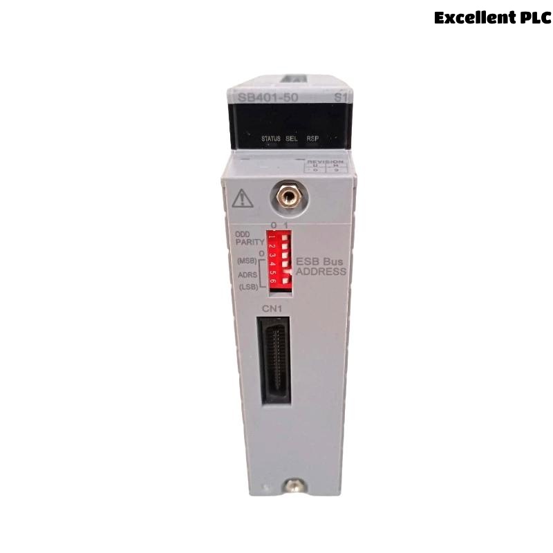
The Yokogawa SB401-50 is an ESB Bus Interface Slave Module used to connect field node units and control stations through the ESB communication network. The module enables high-speed data transfer and supports stable communication between distributed automation devices.
SB401-50 Module Applications
- Distributed Control Systems (DCS)
- Process automation plants
- Oil and gas facilities
- Power generation systems
- Chemical processing plants
- Industrial monitoring networks
ESB Communication Architecture Considerations
- Node address planning
- Communication path allocation
- Bus load balancing
- Redundant communication design
- Controller connectivity strategy
Installation Planning for SB401-50
Before installation, engineers should verify communication drawings, ESB network architecture, node allocation plans, and project database consistency.
- Review engineering database
- Verify hardware compatibility
- Confirm node assignments
- Validate communication topology
- Prepare commissioning procedures
Pre-Installation Inspection
- Verify model identification
- Inspect front panel condition
- Check communication connectors
- Inspect backplane contacts
- Confirm module revision
Environmental Requirements
- Controlled cabinet temperature
- Proper humidity levels
- EMI protection measures
- Adequate ventilation
- Stable mechanical environment
Control Cabinet Preparation
- Verify cabinet grounding
- Inspect cable routing
- Separate signal and power wiring
- Confirm slot allocation
- Label communication cables
Power System Verification
- Measure DC power voltage
- Check power supply redundancy
- Verify grounding continuity
- Review UPS condition
SB401-50 Installation Guide
- Isolate cabinet power.
- Insert the SB401-50 into the assigned slot.
- Secure the locking mechanism.
- Connect ESB communication cables.
- Verify physical installation.
- Restore power and monitor indicators.
ESB Bus Connection Procedure
- Verify cable identification
- Inspect connector engagement
- Confirm bus routing
- Validate network continuity
- Review termination requirements
SB401-50 Setup and Initialization
INSTALL MODULE
POWER ON SYSTEM
VERIFY MODULE STATUS
CONFIGURE NODE ADDRESS
DOWNLOAD CONFIGURATION
ENABLE COMMUNICATION
SAVE PARAMETERS
RESTART NODE
System Configuration Validation
- Node address verification
- Communication parameter validation
- I/O mapping review
- Database consistency check
- Controller communication verification
Communication Verification
- Node online status confirmation
- Communication statistics review
- Packet integrity verification
- Error counter inspection
Commissioning Checklist
- Communication startup test
- Node synchronization verification
- I/O update confirmation
- Alarm validation
- Integrated system testing
Communication Performance Assessment
- Response time measurement
- Network load monitoring
- Error rate analysis
- Data consistency validation
Maintenance Recommendations
- Periodic connector inspection
- Routine communication diagnostics
- Configuration backups
- Network health monitoring
Real Commissioning Case
During startup of a chemical production facility, an SB401-50 failed to establish communication with multiple field nodes.
- Power Supply: 24.1VDC
- Module Status: Normal
- Communication Status: Offline
- Error Counter: Increasing continuously
Initial troubleshooting focused on possible module failure. However, engineering analysis identified an incorrectly configured ESB node address within the project database.
After correcting the address assignment:
- Communication recovered immediately
- Field nodes synchronized normally
- Error counters stopped increasing
- Commissioning completed successfully
In one commissioning case, a configuration review solved a problem that had initially been misdiagnosed as hardware failure.
SB401-50 Installation Guide FAQ
What is the function of the SB401-50 ESB Bus Interface Slave Module?
The module provides communication between field node units and Yokogawa control systems through the ESB bus network.
What should be verified before Setup?
Engineers should verify communication topology, node addresses, power supply quality, and System Configuration settings.
Why is communication testing important during Commissioning?
Communication verification ensures that all nodes exchange data correctly and that the automation system operates reliably.
Summary: Successful SB401-50 Installation, Setup, and Commissioning depend on proper ESB network planning, accurate System Configuration, correct node addressing, and comprehensive communication validation.