

Yokogawa ADV151-D132 Digital Input Module installation failures are most often related to incorrect 24 VDC signal wiring, channel mapping errors, or incomplete System Configuration rather than module hardware problems. Proper Installation Guide procedures help engineers complete Setup and Commissioning efficiently while ensuring reliable acquisition of field status signals throughout the control system. The ADV151 family is a 32-channel isolated Digital Input Module designed for 24 VDC ON/OFF signal monitoring in Yokogawa CENTUM and ProSafe-RS systems. :contentReference[oaicite:0]{index=0}
Contents
- ADV151-D132 Digital Input Module Overview
- ADV151-D132 System Architecture Considerations
- Engineering Planning Before Installation
- Module Inspection Prior to Setup
- Installation Environment Requirements
- Input Signal and Power Verification
- ADV151-D132 Wiring Best Practices
- Digital Input Module Installation Procedure
- ADV151-D132 Setup Procedure
- Input Channel Mapping Validation
- Controller Communication Verification
- Field Signal Testing
- ADV151-D132 Commissioning Process
- Input Signal Optimization
- Routine Maintenance Recommendations
- Real Commissioning Case
- FAQ
ADV151-D132 Digital Input Module Overview
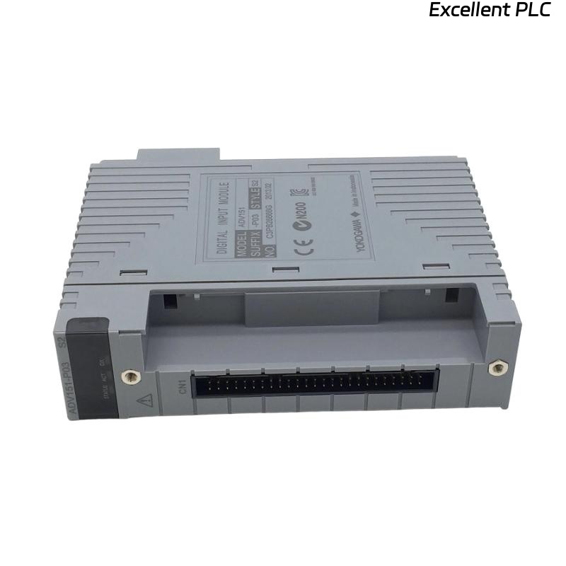
The ADV151 series Digital Input Module supports 32 isolated digital input channels and is designed to receive 24 VDC field status signals from switches, relays, proximity sensors, and process interlock contacts. The module provides reliable signal acquisition for process automation and safety applications. :contentReference[oaicite:1]{index=1}
ADV151-D132 System Architecture Considerations
- Distributed I/O integration
- Process status monitoring
- Alarm input acquisition
- Interlock signal monitoring
- Equipment running feedback
Engineering Planning Before Installation
Before installation, engineering teams should verify cabinet drawings, field wiring schedules, and I/O allocation lists. Most commissioning delays occur because field signal assignments differ from the engineering database.
- Review signal database
- Verify terminal allocation
- Confirm channel assignments
- Validate wiring diagrams
- Check controller database consistency
Module Inspection Prior to Setup
- Verify ADV151-D132 model information
- Inspect module housing condition
- Check connectors for damage
- Review terminal identification
- Confirm project documentation
Installation Environment Requirements
- Maintain cabinet temperature stability
- Control humidity levels
- Minimize vibration exposure
- Reduce electromagnetic interference
- Ensure effective cabinet ventilation
Input Signal and Power Verification
The ADV151 platform is designed for 24 VDC digital input signals with isolated channels. Input voltage verification should be completed before startup. :contentReference[oaicite:2]{index=2}
- Measure signal voltage
- Verify signal polarity
- Check common wiring
- Inspect grounding integrity
- Confirm voltage stability
ADV151-D132 Wiring Best Practices
- Separate signal and power cables
- Use labeled terminal identification
- Maintain proper shielding practices
- Avoid parallel routing with VFD cables
- Verify terminal torque values
Digital Input Module Installation Procedure
- Isolate cabinet power.
- Insert ADV151-D132 into the assigned slot.
- Secure module locking mechanisms.
- Connect field signal wiring.
- Verify terminal assignments.
- Restore system power.
- Check module indicators.
ADV151-D132 Setup Procedure
INSTALL MODULE
POWER ON SYSTEM
VERIFY MODULE STATUS
CONFIGURE INPUT CHANNELS
DOWNLOAD DATABASE
VALIDATE SIGNAL TAGS
SAVE CONFIGURATION
PERFORM STARTUP TEST
Input Channel Mapping Validation
- Verify tag assignments
- Check channel descriptions
- Confirm alarm linkage
- Review interlock references
- Validate operator displays
Controller Communication Verification
- Verify controller connectivity
- Check I/O scan updates
- Inspect diagnostic status
- Review communication logs
Field Signal Testing
- Activate field contacts
- Monitor input status changes
- Verify alarm generation
- Confirm event recording
- Validate logic execution
ADV151-D132 Commissioning Process
Commissioning should focus on actual process signals rather than simulation alone. Testing real field devices identifies wiring mistakes that often remain hidden during database validation.
Input Signal Optimization
- Improve grounding quality
- Reduce electrical noise
- Separate high-current circuits
- Monitor signal stability trends
Routine Maintenance Recommendations
- Inspect terminal blocks regularly
- Review diagnostic alarms
- Verify signal integrity
- Maintain configuration backups
Real Commissioning Case
During startup of a petrochemical utility unit, twelve ADV151-D132 input points remained inactive despite healthy field instruments.
- Input Voltage: 24.2 VDC
- Controller Communication: Normal
- Module Diagnostics: Healthy
- Inactive Channels: 12
Engineers initially suspected a faulty Digital Input Module. However, signal tracing revealed that field cables had been landed on an adjacent terminal strip during cabinet assembly.
After correcting the wiring:
- All 12 channels became active
- Alarm functions operated normally
- Interlock testing passed
- Commissioning finished ahead of schedule
In one commissioning case, incorrect terminal termination produced symptoms identical to a hardware fault.
ADV151-D132 Installation Guide FAQ
What signals can the ADV151-D132 monitor?
The module monitors 24 VDC digital signals from switches, relays, proximity sensors, valve feedback contacts, and equipment status indicators.
Why should channel mapping be validated during Setup?
Incorrect channel mapping can create false alarms, incorrect operator indications, and unexpected control logic behavior.
What is the most common installation issue?
Field wiring termination errors remain one of the most common causes of commissioning delays.
Summary: Successful ADV151-D132 Installation, Setup, and Commissioning depend on accurate wiring, validated System Configuration, correct channel mapping, and comprehensive field signal testing.