

Yokogawa ADV151-P53/D5A00 Digital Input Module installation problems are typically caused by incorrect KS cable termination, channel allocation mistakes, or grounding deficiencies rather than hardware failure. Proper Setup and Commissioning are critical because this 32-channel isolated Digital Input Module acquires 24 VDC field signals and supports pushbutton input functions in CENTUM VP and ProSafe-RS systems. :contentReference[oaicite:0]{index=0}
Contents
- ADV151-P53/D5A00 Digital Input Module Overview
- ADV151-P53/D5A00 Technical Specifications
- ADV151-P53/D5A00 Installation Planning
- ADV151-P53/D5A00 Environmental Requirements
- ADV151-P53/D5A00 Incoming Inspection
- ADV151-P53/D5A00 Power Verification
- ADV151-P53/D5A00 KS Cable Interface Adapter Setup
- ADV151-P53/D5A00 Wiring Installation Guide
- ADV151-P53/D5A00 Grounding and Shielding
- ADV151-P53/D5A00 Module Mounting Procedure
- ADV151-P53/D5A00 System Configuration
- ADV151-P53/D5A00 Input Verification
- ADV151-P53/D5A00 Commissioning Workflow
- ADV151-P53/D5A00 Performance Optimization
- ADV151-P53/D5A00 Maintenance Strategy
- Real Commissioning Case
- FAQ
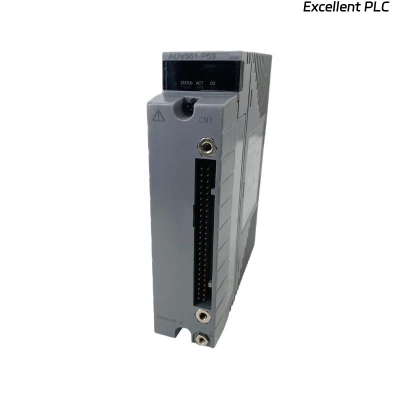
ADV151-P53/D5A00 Digital Input Module Overview
The ADV151-P53/D5A00 is a 32-channel isolated Digital Input Module designed for 24 VDC signal acquisition. The module includes pushbutton input capability, ISA G3 environmental protection, an operating temperature range of -20°C to 70°C, and a KS Cable Interface Adapter (ATD5A-00). :contentReference[oaicite:1]{index=1}
ADV151-P53/D5A00 Technical Specifications
- 32 isolated input channels
- 24 VDC rated input voltage
- 18–26.4 VDC ON detection range
- 5 VDC or less OFF detection threshold
- 8 ms response time
- ISA G3 environmental protection
- KS Cable Interface Adapter included
- Operating temperature: -20°C to 70°C
ADV151-P53/D5A00 Installation Planning
Successful Installation Guide implementation starts with reviewing I/O allocation tables, loop drawings, cabinet layouts, and signal lists. Most commissioning delays originate from documentation inconsistencies rather than module defects.
ADV151-P53/D5A00 Environmental Requirements
- Proper ventilation
- Corrosion-controlled environment
- Reliable cabinet grounding
- Low vibration installation area
- Stable ambient temperature
ADV151-P53/D5A00 Incoming Inspection
- Verify model number
- Inspect module housing
- Check connector integrity
- Verify KS adapter condition
- Review shipping records
ADV151-P53/D5A00 Power Verification
- Measure system voltage
- Verify polarity
- Inspect common return wiring
- Confirm power stability
ADV151-P53/D5A00 KS Cable Interface Adapter Setup
The D5A00 option uses the ATD5A-00 KS Cable Interface Adapter to simplify high-density signal termination and reduce wiring complexity. Proper adapter installation significantly improves commissioning efficiency. :contentReference[oaicite:2]{index=2}
- Inspect adapter connectors
- Verify cable orientation
- Check locking mechanisms
- Confirm channel assignments
ADV151-P53/D5A00 Wiring Installation Guide
- Separate power and signal cables
- Use approved cable routing paths
- Verify terminal numbering
- Inspect continuity before energization
- Label all field conductors
ADV151-P53/D5A00 Grounding and Shielding
- Apply single-point grounding
- Terminate shields correctly
- Avoid multiple earth connections
- Inspect cabinet bonding
ADV151-P53/D5A00 Module Mounting Procedure
- Isolate cabinet power.
- Install module in assigned slot.
- Secure locking mechanism.
- Connect KS cable adapter.
- Verify terminal assignments.
- Restore power.
- Observe module diagnostics.
ADV151-P53/D5A00 System Configuration
SCAN HARDWARE
DETECT MODULE
ASSIGN CHANNELS
CREATE TAGS
DOWNLOAD DATABASE
VERIFY PARAMETERS
SAVE CONFIGURATION
ENABLE OPERATION
ADV151-P53/D5A00 Input Verification
- Operate field switches
- Verify input response
- Check alarm functionality
- Confirm SOE recording
- Validate operator graphics
ADV151-P53/D5A00 Commissioning Workflow
Commissioning should include actual field device operation. Live testing often identifies wiring and marshalling issues not visible during simulation.
ADV151-P53/D5A00 Performance Optimization
- Improve cable segregation
- Reduce EMI exposure
- Optimize grounding network
- Verify shield continuity
ADV151-P53/D5A00 Maintenance Strategy
- Inspect terminals annually
- Review diagnostics regularly
- Check grounding resistance
- Maintain configuration backups
Real Commissioning Case
During startup of an offshore platform control system, 12 ADV151-P53/D5A00 channels failed to update equipment status.
- Measured Voltage: 24.1 VDC
- Input Current: 4.0 mA
- Module Status: Healthy
- Affected Channels: 12
We observed that all affected signals were routed through a single KS adapter cable. Detailed inspection revealed that the cable connector had not fully engaged during installation.
After reconnecting the cable:
- All channels recovered
- SOE events were recorded correctly
- Alarm functions operated normally
- Commissioning completed without hardware replacement
ADV151-P53/D5A00 Installation FAQ
What is the purpose of the D5A00 option?
The D5A00 option provides a KS Cable Interface Adapter for simplified 32-channel signal termination. :contentReference[oaicite:3]{index=3}
Can the module operate in corrosive environments?
Yes. The P53 version includes ISA G3 environmental protection and extended temperature capability. :contentReference[oaicite:4]{index=4}
What causes most commissioning issues?
Incorrect channel assignments, cable termination errors, and grounding problems are more common than module hardware failures.
Summary: Reliable ADV151-P53/D5A00 Installation, Setup, and Commissioning depend on proper KS cable integration, accurate System Configuration, effective grounding, and comprehensive field testing.