

Yokogawa ADV151-H50/D5A00 Digital Input Module installation issues are most frequently caused by incorrect field signal wiring, improper cabinet grounding, or incomplete System Configuration rather than hardware defects. A disciplined Installation Guide helps engineers complete Setup and Commissioning efficiently while ensuring reliable signal acquisition in critical industrial automation environments.
Contents
- ADV151-H50/D5A00 Digital Input Module Overview
- ADV151-H50/D5A00 Application Architecture
- ADV151-H50/D5A00 Engineering Preparation
- ADV151-H50/D5A00 Incoming Inspection
- ADV151-H50/D5A00 Installation Environment
- ADV151-H50/D5A00 Signal Requirements
- ADV151-H50/D5A00 Cabinet Installation Strategy
- ADV151-H50/D5A00 Wiring Best Practices
- ADV151-H50/D5A00 Grounding and Shielding
- ADV151-H50/D5A00 Setup Procedure
- ADV151-H50/D5A00 System Configuration
- ADV151-H50/D5A00 Validation Testing
- ADV151-H50/D5A00 Commissioning Process
- ADV151-H50/D5A00 Performance Optimization
- ADV151-H50/D5A00 Maintenance Guidelines
- Real Commissioning Case
- FAQ
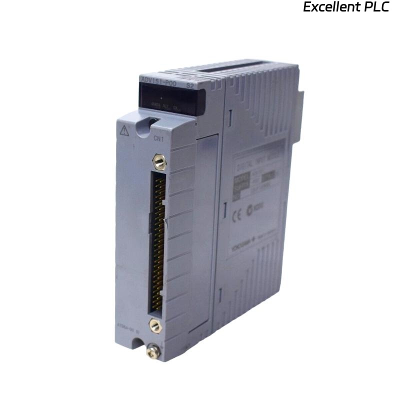
ADV151-H50/D5A00 Digital Input Module Overview
The Yokogawa ADV151-H50/D5A00 Digital Input Module is designed to monitor field status signals from switches, relays, limit switches, emergency shutdown contacts, and process equipment. The module provides high-reliability signal acquisition for industrial control and safety-related applications.
ADV151-H50/D5A00 Application Architecture
- Motor status monitoring
- Valve position feedback
- Safety interlock systems
- Emergency shutdown monitoring
- Equipment availability tracking
- Process alarm acquisition
ADV151-H50/D5A00 Engineering Preparation
Successful Setup begins long before hardware installation. Engineering teams should review the complete signal path from field devices to controller databases.
- Verify I/O allocation drawings
- Review control narratives
- Confirm cabinet layouts
- Check terminal schedules
- Validate controller compatibility
ADV151-H50/D5A00 Incoming Inspection
- Confirm model number
- Inspect housing integrity
- Verify connector condition
- Check shipment records
- Review installation documentation
ADV151-H50/D5A00 Installation Environment
- Stable operating temperature
- Low relative humidity
- Proper cabinet ventilation
- Minimal vibration exposure
- Reliable grounding network
ADV151-H50/D5A00 Signal Requirements
Before installation, engineers should verify field input characteristics.
- 24 VDC signal availability
- Correct polarity
- Stable common reference
- Signal integrity verification
- Noise level assessment
ADV151-H50/D5A00 Cabinet Installation Strategy
- Install within approved slots
- Maintain airflow clearances
- Avoid heat source proximity
- Label module positions clearly
- Verify mechanical locking
ADV151-H50/D5A00 Wiring Best Practices
- Separate signal and power wiring
- Use identified conductors
- Maintain cable shielding continuity
- Avoid parallel routing with VFD cables
- Inspect terminal torque values
ADV151-H50/D5A00 Grounding and Shielding
Field experience shows that many digital input problems originate from poor grounding and shielding practices.
- Apply single-point grounding
- Eliminate ground loops
- Inspect shield termination points
- Measure grounding resistance
ADV151-H50/D5A00 Setup Procedure
INSTALL MODULE
APPLY SYSTEM POWER
VERIFY MODULE STATUS
ASSIGN CHANNELS
CONFIGURE TAGS
DOWNLOAD DATABASE
SAVE PARAMETERS
START TESTING
ADV151-H50/D5A00 System Configuration
- Verify channel mapping
- Confirm tag assignments
- Review alarm configuration
- Validate event recording
- Check logic references
ADV151-H50/D5A00 Validation Testing
- Activate field contacts
- Observe channel transitions
- Verify alarm responses
- Review operator displays
- Check event records
ADV151-H50/D5A00 Commissioning Process
Commissioning should focus on live field equipment rather than simulation alone. Real device testing often identifies wiring errors hidden during software validation.
- Field device testing
- Alarm verification
- Logic validation
- Operator display review
ADV151-H50/D5A00 Performance Optimization
- Improve cable routing
- Enhance grounding quality
- Reduce EMI exposure
- Monitor signal trends
ADV151-H50/D5A00 Maintenance Guidelines
- Inspect terminals annually
- Review diagnostic logs
- Verify grounding integrity
- Maintain database backups
Real Commissioning Case
During startup of a gas compression station, operators reported that several compressor permissive signals connected to an ADV151-H50/D5A00 module were not updating correctly.
- Measured Input Voltage: 24.3 VDC
- Module Status: Normal
- Controller Communication: Healthy
- Affected Inputs: 12 Channels
Engineers initially suspected a defective Digital Input Module. Detailed signal tracing revealed that a marshalling cabinet common return terminal had been connected incorrectly during construction.
After correcting the wiring:
- All channels responded normally
- Alarm functions operated correctly
- Control logic executed properly
- Commissioning completed on schedule
In one commissioning case, proper wiring verification avoided unnecessary hardware replacement and reduced startup delays.
ADV151-H50/D5A00 Installation Guide FAQ
What signals can the ADV151-H50/D5A00 Digital Input Module monitor?
The module monitors digital status signals from switches, relays, valve feedback contacts, emergency shutdown systems, and industrial field devices.
Why is System Configuration important during Setup?
Incorrect channel assignments can lead to false alarms, operator display errors, and improper control logic execution.
What is the most common commissioning issue?
Field wiring errors and common return wiring mistakes are significantly more common than actual module hardware failures.
Summary: Successful ADV151-H50/D5A00 Installation, Setup, and Commissioning require correct wiring, validated System Configuration, reliable grounding, and comprehensive field signal verification.