

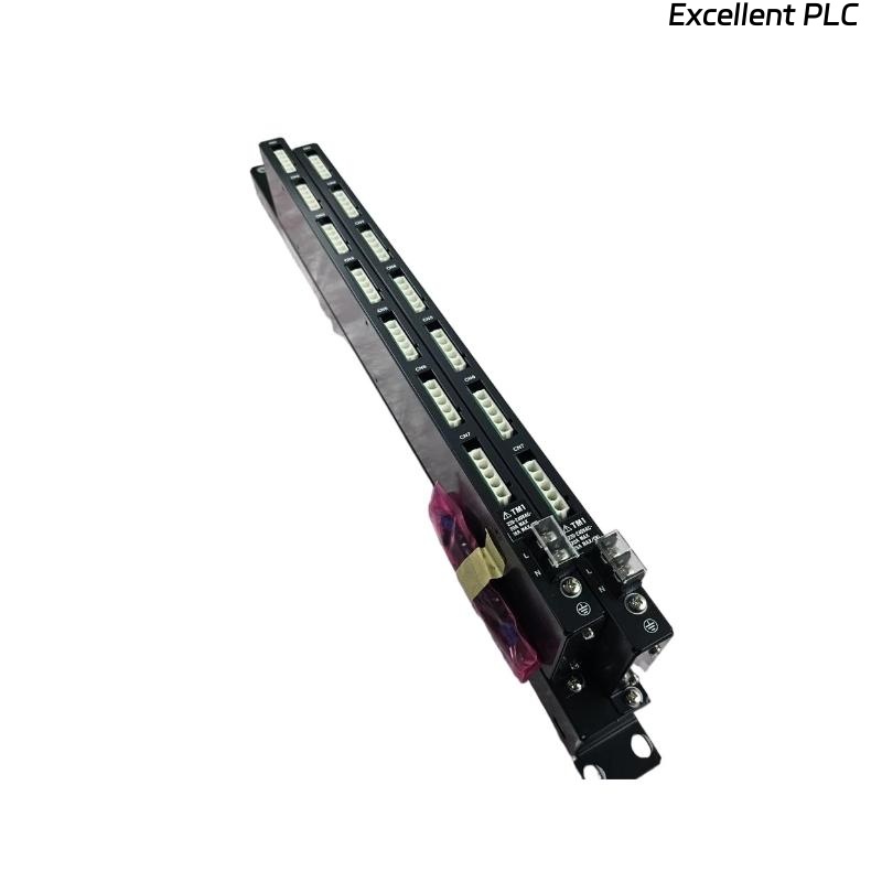
The Yokogawa AEP9D Secondary Power Supply Bus Unit distributes regulated 24 VDC power from PW601 or PW602 power supply modules to multiple devices within a Yokogawa CENTUM VP FIO cabinet. As a passive power distribution unit, the AEP9D contains no active electronic control circuitry. Most reported faults are caused by loose wiring, overloaded outputs, damaged connectors, incorrect polarity, or grounding problems rather than failures within the bus unit itself. A systematic troubleshooting procedure allows maintenance engineers to identify the source of power distribution issues quickly and restore reliable cabinet operation.
Contents
- 1. Understanding AEP9D Power Distribution Faults
- 2. Common Failure Symptoms
- 3. Typical Causes of Secondary Power Problems
- 4. Visual Inspection Procedure
- 5. Input Power Verification
- 6. Output Distribution Inspection
- 7. Grounding Inspection
- 8. Electrical Measurements
- 9. Recommended Troubleshooting Workflow
- 10. Corrective Actions
- 11. Functional Recovery Verification
- 12. Preventive Maintenance
- 13. Environmental Considerations
- 14. Real Industrial Maintenance Case
- 15. Frequently Asked Questions
- 16. Summary
Understanding AEP9D Power Distribution Faults
The AEP9D serves as the secondary 24 VDC power distribution point inside the FIO cabinet. Since it performs only power distribution, failures generally originate from external electrical connections, excessive current demand, damaged conductors, or poor installation practices.
Before replacing the bus unit, maintenance personnel should verify the upstream PW601 or PW602 power supply, input voltage, wiring integrity, and downstream equipment.
Common Failure Symptoms
- 24 VDC output missing on one or more branches
- Multiple I/O modules lose power simultaneously
- Intermittent cabinet operation
- Voltage drops under heavy load
- Controller reports power-related alarms
- Fieldbus devices fail to initialize
- Output connectors become warm during operation
Typical Causes of Secondary Power Problems
- Loose input connectors
- Loose output connectors
- Incorrect polarity
- Damaged power cables
- Overloaded output circuits
- Poor cabinet grounding
- Connector oxidation
- Improper redundant wiring
Visual Inspection Procedure
- Inspect all power connectors
- Check terminal discoloration
- Inspect cable insulation
- Verify connector locking
- Inspect cabinet wiring organization
Input Power Verification
Always verify the upstream power supply before troubleshooting downstream distribution circuits.
- Measure 24 VDC input voltage
- Verify input polarity
- Inspect power supply status indicators
- Check upstream protective devices
- Confirm redundant input operation
Output Distribution Inspection
- Measure voltage at each output connector
- Compare voltage between output groups
- Inspect connector engagement
- Verify load allocation
- Inspect downstream wiring
Grounding Inspection
- Verify protective earth continuity
- Inspect cabinet bonding
- Measure grounding resistance
- Inspect grounding conductors
- Avoid unnecessary grounding loops
Electrical Measurements
| Measured Condition | Possible Diagnosis |
|---|---|
| 24 VDC at input, no output | Loose output connector or open conductor |
| Low output voltage | High resistance connection or overload |
| No input voltage | Power supply failure or upstream wiring problem |
| Stable input and output voltage | Normal power distribution |
| Intermittent output voltage | Loose connector or damaged cable |
Voltage measurements should be performed while the connected equipment is operating to detect hidden voltage drops caused by poor electrical connections.
Recommended Troubleshooting Workflow
VERIFY PW601 OR PW602 OUTPUT
CHECK INPUT VOLTAGE
INSPECT CONNECTORS
MEASURE OUTPUT VOLTAGES
VERIFY LOAD DISTRIBUTION
CHECK GROUNDING
TEST DOWNSTREAM DEVICES
IDENTIFY ROOT CAUSE
VALIDATE REPAIR
Following a logical troubleshooting sequence minimizes maintenance time and reduces unnecessary replacement of passive distribution hardware.
Corrective Actions
- Reconnect loose power connectors
- Replace damaged conductors
- Correct polarity errors
- Redistribute electrical loads
- Clean oxidized terminals
- Restore cabinet grounding
- Replace the AEP9D only if physical damage or burned conductors prevent safe power distribution
Functional Recovery Verification
- Measure voltage at every output connector
- Verify all connected equipment powers correctly
- Test redundant input operation
- Monitor voltage stability under load
- Record maintenance activities
Preventive Maintenance
- Inspect connectors every six months
- Verify output voltage annually
- Retighten power connections
- Review cabinet load distribution
- Maintain current wiring documentation
Environmental Considerations
Environmental conditions directly influence the long-term reliability of power distribution equipment.
- Maintain cabinet temperature within specifications
- Prevent moisture accumulation
- Minimize vibration
- Protect against corrosive contaminants
- Keep cabinet interiors clean
Real Industrial Maintenance Case
During maintenance at a pharmaceutical manufacturing facility, operators reported that several remote I/O stations unexpectedly shut down while the primary power supply continued to indicate normal operation.
Measurements confirmed that the PW602 power supply delivered a stable 24 VDC output. Further inspection of the AEP9D revealed that one output connector feeding multiple remote I/O devices had developed increased contact resistance because of insufficient connector engagement.
After disconnecting the power, reseating the connector, cleaning the contacts, and verifying all output connections:
- All remote I/O stations restarted successfully.
- Output voltage remained stable under full load.
- No additional power interruptions occurred during extended testing.
- The AEP9D remained fully operational without replacement.
This case demonstrates that connector integrity and proper load distribution should always be verified before replacing secondary power distribution equipment.
Frequently Asked Questions
Does the AEP9D regulate output voltage?
No. The AEP9D only distributes regulated 24 VDC power received from the PW601 or PW602 power supply module. Voltage regulation is performed by the power supply itself.
Why do only some devices lose power?
This usually indicates a loose output connector, damaged branch cable, overloaded output circuit, or poor electrical contact affecting one distribution path.
When should the AEP9D be replaced?
Replacement should be considered only when the unit has severe mechanical damage, burned connectors, cracked insulation, or internal conductor damage that prevents reliable power distribution.
Summary
Effective troubleshooting of the Yokogawa AEP9D Secondary Power Supply Bus Unit involves verifying upstream 24 VDC power, inspecting input and output connections, measuring voltage under operating conditions, checking grounding integrity, and confirming balanced load distribution. Following a structured diagnostic process helps restore reliable secondary power, reduce downtime, and prevent unnecessary replacement of passive power distribution components.