

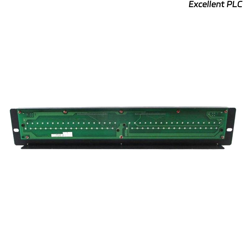
The Yokogawa AED5D Digital Terminal Board is a passive field wiring interface used in Yokogawa FIO systems to connect digital input and digital output modules with field devices. Because the terminal board contains no active electronic components, most operational problems originate from loose terminals, damaged connection cables, incorrect field wiring, poor grounding, or environmental conditions. A systematic troubleshooting procedure helps maintenance personnel quickly identify wiring faults, restore signal integrity, and minimize unnecessary replacement of I/O modules.
Contents
- 1. Understanding AED5D Terminal Board Faults
- 2. Common Failure Symptoms
- 3. Typical Causes of Wiring Problems
- 4. Visual Inspection Procedure
- 5. Wiring and Terminal Diagnosis
- 6. AKB Cable Inspection
- 7. Cable Continuity Testing
- 8. Grounding and Shield Verification
- 9. Electrical Measurements
- 10. Recommended Troubleshooting Workflow
- 11. Corrective Actions
- 12. Functional Recovery Verification
- 13. Preventive Maintenance
- 14. Environmental Considerations
- 15. Real Industrial Maintenance Case
- 16. Frequently Asked Questions
Understanding AED5D Terminal Board Faults
The AED5D functions as a passive wiring interface between digital I/O modules and field equipment. Since it contains no active circuitry, failures are usually associated with mechanical or electrical connection issues rather than defects within the terminal board itself.
Before replacing the terminal board, maintenance personnel should verify field wiring, connection cables, controller diagnostics, and the associated digital I/O module.
Common Failure Symptoms
- Digital input channels remain inactive
- Digital output devices fail to operate
- Intermittent I/O operation
- Multiple adjacent channels fail simultaneously
- Unexpected controller I/O alarms
- Communication appears normal but field devices do not respond
- Loose or unstable terminal connections
Typical Causes of Wiring Problems
- Loose M4 terminal screws
- Incorrect field wiring
- Damaged AKB331 or AKB337 cable
- Poor connector engagement
- Broken conductors
- Grounding faults
- Corrosion on terminals
- Mechanical vibration
Visual Inspection Procedure
- Inspect all terminal screws
- Check connector locking mechanisms
- Inspect cable insulation
- Verify terminal labels
- Look for corrosion or contamination
Wiring and Terminal Diagnosis
Most field problems can be identified by comparing installed wiring with approved engineering documentation.
- Verify terminal assignments
- Inspect conductor insertion
- Confirm tightening torque
- Check conductor polarity where required
- Verify cable routing
AKB Cable Inspection
- Verify connector locking
- Inspect cable strain relief
- Check connector pins
- Inspect for bent contacts
- Reconnect securely
Cable Continuity Testing
- Disconnect field wiring safely
- Measure conductor continuity
- Verify insulation resistance
- Check for short circuits
- Reconnect after testing
Grounding and Shield Verification
- Verify cabinet grounding
- Inspect shield termination
- Avoid multiple grounding points
- Measure earth continuity
- Inspect bonding conductors
Electrical Measurements
| Measured Condition | Possible Diagnosis |
|---|---|
| Open circuit | Broken conductor or loose terminal |
| High resistance | Poor terminal contact or corrosion |
| Intermittent continuity | Loose cable or damaged connector |
| Stable continuity | Normal wiring condition |
| Unexpected voltage drop | Loose terminal or damaged conductor |
Electrical testing should be performed with circuits isolated whenever possible to ensure accurate resistance and continuity measurements.
Recommended Troubleshooting Workflow
CHECK CONTROLLER DIAGNOSTICS
INSPECT TERMINAL BOARD
VERIFY FIELD WIRING
CHECK AKB CONNECTION CABLE
MEASURE CONTINUITY
VERIFY GROUNDING
TEST FIELD DEVICES
IDENTIFY ROOT CAUSE
VALIDATE REPAIR
A structured troubleshooting sequence minimizes maintenance time and helps distinguish wiring faults from I/O module problems.
Corrective Actions
- Retighten loose terminal screws
- Replace damaged field conductors
- Repair or replace AKB connection cables
- Correct terminal assignments
- Clean oxidized terminals
- Restore proper grounding
- Replace the terminal board only if physical damage prevents reliable electrical connections
Functional Recovery Verification
- Verify all digital input channels
- Verify all digital output channels
- Confirm controller diagnostics
- Test field equipment repeatedly
- Document maintenance results
Preventive Maintenance
- Inspect terminals every six months
- Retighten screws when necessary
- Inspect AKB cables annually
- Maintain cabinet cleanliness
- Update wiring documentation after modifications
Environmental Considerations
Long-term reliability depends on maintaining suitable environmental conditions inside the control cabinet.
- Prevent excessive humidity
- Avoid condensation
- Minimize vibration
- Protect against corrosive gases
- Maintain proper cabinet ventilation
Real Industrial Maintenance Case
During maintenance of a water treatment facility, operators reported that eight digital input channels connected through an AED5D terminal board stopped responding after routine cabinet cleaning.
Controller diagnostics indicated that the associated digital input module was operating normally. Inspection revealed that the AKB331 connection cable had not been fully secured after maintenance work, resulting in intermittent contact between the module and the terminal board.
After reconnecting and locking the cable, followed by verification of all terminal screws:
- All digital input channels returned to normal operation.
- Controller alarms cleared automatically.
- No hardware replacement was required.
- The system remained stable during extended operational testing.
This case demonstrates that connector engagement should always be verified before replacing passive wiring components or digital I/O modules.
Frequently Asked Questions
Does the AED5D contain active electronic components?
No. The AED5D is a passive terminal board designed to provide reliable field wiring connections between digital I/O modules and external equipment.
What is the most common cause of AED5D-related faults?
Loose terminal screws, partially connected AKB cables, damaged field wiring, poor grounding, and incorrect terminal assignments account for most reported issues.
When should the AED5D terminal board be replaced?
Replacement is recommended only if the board has cracked insulation, damaged connectors, broken terminals, severe corrosion, or mechanical damage that prevents reliable electrical connections.
Summary: Effective troubleshooting of the Yokogawa AED5D Digital Terminal Board focuses on systematic inspection of wiring, terminal integrity, AKB connection cables, grounding, and field devices. By following a structured diagnostic workflow, maintenance engineers can restore reliable digital signal transmission, reduce downtime, and avoid unnecessary replacement of associated I/O modules.